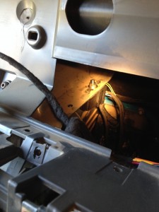
Here’s how I installed a retarder to my Iveco Daily 4×4.
The Problem
After 18 months of operating our Iveco Daily 4×4 55S17W (otherwise known as ‘Cuthbert’ to his friends) we can say that it is a really great truck. However, like many other users we have spoken to we are very disappointed with the brakes. The problems are not significant with general driving around flat and low-hilly areas where only minimal braking is required, but in descents of long, steep mountain roads the weaknesses manifest themselves with potentially very serious consequences. Is an electro retarder the solution?
The vehicle has a fairly standard set up of a hydraulic system with basic ABS (Bosch 5.3, which doesn’t have any of the advanced stability controls, only ‘anti-blocking’). Our concern centres on three main points: the absence of any engine braking; the front axle having un-ventilated discs; and the rear axle having only drums brakes.
The standard Iveco Daily 4×4 has a GVW of 5500 kg and can tow a 750 kg un-braked trailer, giving a total mass to brake of 6250 kg. As Cuthbert has been re-plated to increase the maximum GVW, we operate at 5900 kg without a trailer, some 350 kg below the maximum for which the brakes have been designed to operate. The highly efficient and clean Euro 5 EEV 3-litre engine is quite small considering the total vehicle mass. This small engine capacity means that there is no effective engine braking during hill descents.
We have often found that even in 1st gear with the half gear engaged, the vehicle ‘runs away’ even at speeds as low as 12 kph on some steep descents! This leads to the use of either the low range gears or the brake pedal. Having the engine sat at high revs for long periods during hill descents is not good for either the engine, the gearboxes or the whole transmission system. On some tarred roads, there is also a considerable risk of much faster traffic running into the back of such a slow moving vehicle! Unfortunately, using the brakes even at speeds as low as 15 or 20 kph quickly leads to them overheating and failing. This has happened to us twice so far (once in the Alps in Europe and again in Lesotho, Africa) and we can say from experience… it’s not nice!
The Options
What to do about it? We considered three options to improve the situation:-
- Upgrade the existing brakes.
- Increase the engine braking with an exhaust brake.
- Add another braking system.
Option 1 – Upgrading the existing brakes
All the other vehicles in the Iveco Daily range (i.e. the 4×2 vehicles) have ventilated discs at the front and a combined disc/drum brake at the rear – a good design. Unfortunately the design of the front axle on the 4×4 is very old-fashioned and it is not possible to easily install the modern vented discs on the 4×4 truck.
Option 2 – Increase the engine braking with an exhaust brake
Mitsubishi use the same Iveco engine in some of their vehicles. They have chosen to use an exhaust brake but have a different design of manifold. ‘Goingbush’ in Australia has installed an exhaust brake on an Iveco Daily 4×4 (see: http://www.goingbush.com/iveco.html) but to do this he has had to disable the EGR and DPF to allow it to work without engine issues. This is not legally allowed in Europe and it potentially invalidates the engine warranty.
Option 3 – Add another braking system
Iveco offers the Telma electro retarder as an option on the Daily 4×2 range. The electro retarder is installed in the prop-shaft between the gearbox and rear axle. It is in effect an electric brake that can be applied using a hand controller and helps to reduce the speed of the vehicle by slowing down the prop-shaft – basically having the same effect as engine braking but with much more power.
The Solution
Having weighed it all up, we have decided to go with Option 3 and install a Telma electro retarder.
Electro retarder – Principle of operation
The retarder consists of a stator which has 3 pairs of electro magnets and is attached to the chassis. A shaft passes through the stator and has a rotor attached on either side of the stator; the prop-shafts are connected to either end of this shaft. When you require braking, you apply power to the electro magnets. Depending on the amount of braking you require, the power will be applied to either one, two or all three sets of magnets.
The magnetic field generated by the electro magnets sets up eddy currents in the aluminium rotors. As the rotors are spinning, these eddy currents resist the magnetic field and this produces the braking effect. For a fuller description see: http://www.emrtech.co.uk/11.html . The advantages of this system are that there are no parts to wear-out and the heat generated in the rotors is dispersed by the airflow across the spinning rotor (the rotors have cooling fins).
Where to install the retarder
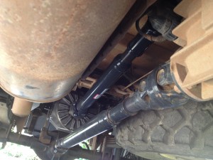
The conventional installation is in the prop-shaft leading to the rear axle. This has been done by Telma on the Daily 4×4 but their design has two disadvantages: first it requires the removal of the spare wheel carrier under the vehicle, and secondly it compromises the ground clearance and bridging angle. However, with a little lateral thinking I have installed it above the rear axle and with a prop-shaft connection to the Power Take Off (PTO) on the transfer gearbox.
Is the PTO strong enough?
I am using the Telma AF30-35 electro retarder that produces a maximum torque of 350 Nm. The transfer gearbox has 4 optional PTOs: options 8693, 8694, 8695 and 8696. Iveco has confirmed to me informally that the PTO options have maximum transmittable torque of 120 Nm, 150 Nm, 350 Nm and 1900 Nm respectively. I have chosen option 8696 PTO as it has the highest transmittable torque and a drive flange fitting which allows a prop-shaft to be attached.
I have tried to contact Iveco to formally confirm these specifications, but my emails seemed to get bounced around and I was eventually told to contact our local Iveco dealer. The local dealers either didn’t respond to emails at all, or replied with questions such as “what is a transfer gearbox?” This apparent ignorance of the basic Daily 4×4 vehicle does not inspire confidence in any further information that may subsequently be forthcoming!
To double check the specifications, I have had a detailed look at the design of the transfer gearbox and PTO. The transfer gearbox input shaft passes right through the transfer case and is connected directly to the PTO without any gearing (a very strong design). The nose of the PTO drive shaft sits within a needle roller bearing, which is within the end of the gearbox’s input shaft. There is a set of toothed cogs: one is attached to the input shaft and the other one slides on the PTO drive shaft to engage/dis-engage the power from the input shaft to the PTO drive shaft.
According to SCAM technical data (I cannot find any data from Iveco) the gearbox has a 1100 Nm torque capacity. The engine can produce a maximum torque of 400 Nm and the retarder can produce 350 Nm. From this it seems that the retarder produces less torque than the engine can put through the gearbox (the retarder would put through the same forces as driving in reverse), which is well within the limits of the input shaft’s 1100 Nm torque.
My conclusion is that the PTO and transfer gearbox should be able to take the loads applied by the retarder.
Mechanical Installation
I had some design considerations for the installation:
- The installation should not interfere with the original vehicle brake or transmission configuration.
- There needs to be clearance between the bottom of the retarder and the rear axle prop-shaft when the suspension is fully compressed and the retarder is at maximum deflection within its anti-vibration mounts.
- Heat shielding is required for temperature sensitive components near the retarder’s rotors.
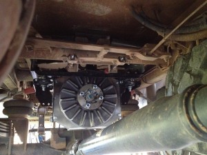
I have mounted the retarder between and below the two tubular chassis cross members, just forward of the rear axle. This section of the chassis is designed for mounting the hydraulic ram for a tipper-tray, so it is very strong. The approximate static load on either side of the chassis will be 35 kg. However, during maximum retarder braking this will change to an approximate down-force equivalent to 95 kg on one side and an up-force equivalent to 25 kg on the other side (I am using a mass (kg) rather than force (Newtons) as it is easier for most people to equate too).
Between the two tubular chassis cross members on either side, there are ‘C’ sections of 3.5 mm thick steel. These are 40 mm high and have 20 mm top and bottom flanges (the top flanges actually extend to the side rails of the chassis but have holes cut into the flange, the narrowest sections giving a flange distance of 20 mm). These sections are fully welded into the chassis tubes at either end and I have attached retarder brackets to these sections.
I have made the retarder brackets using two 100 x 100 x 6 mm stainless steel (310) angles, which fit between the retarder’s anti-vibration mounts and the chassis. To reduce any twisting forces on the chassis mounting points, I have also cross braced these brackets with two 20 x 20 x 3 mm stainless steel angles. This stainless steel should provide good resistance to corrosion and is non-magnetic so should not be effected by the magnetic fields within the retarder.
To allow for reasonable chassis clearances and to ensure the maximum retarder to rear axle prop-shaft clearance, the retarder has been mounted as far aft as possible. The vertical position has been a compromise between: the PTO prop-shaft angle, the clearance of the hand brake cables and the clearance of the rear axle prop-shaft. The hand-brake cables have a heat protection ‘fire sleeve’ fitted as a precaution to give them protection from the hot airflow coming off of the retarders rotors during extended retarder braking.
Some aluminium sheets have been attached to the retarder brackets and heat protection sleeves have been inserted around wires. These provide heat shielding to protect sensitive components from the hot airflow coming from the retarder’s rotors during extended operations of the retarder on long hill descents.
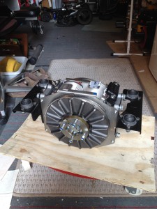
- Retarder with Telma supplied brackets
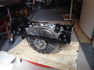
- My brackets to attache the retarder to the chassis
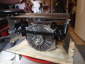
- With heat shields attached
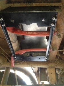
- Bracket fitted to chassis with top heat shield and fire sleeve on handbrake cables
- Retarder mounted in the chassis
To connect the retarder to the PTO, I have used the front prop-shaft that is standard for our truck. This standard prop-shaft just happens to be the correct length and using it means that we are now carrying a spare for the front axle should we need it in a remote area sometime.
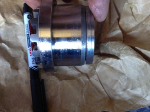
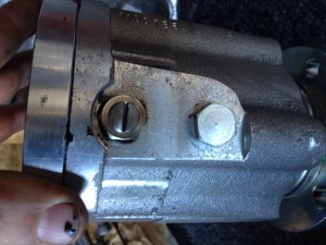
The PTO is designed to be engaged and disengaged using hydraulic pressure from the APU. However, in this application it is required to be permanently engaged. The PTO was therefore modified by ‘shimming’ the engagement piston into the engaged position (8 mm of shims allowing a small gap for thermal expansion). Blanking plugs were installed in the hydraulic and engagement sensor holes to seal the unit.
- PTO connection shaft on the back of the Transfer Case
- PTO cog and needle roller bearing installed
- Oil control plate in position – I needed to remove the cog to fit it
- 8 mm of shims on the back of the PTO cog engagment piston
- PTO cog shimed into the engagment position shown with oil control plate
- M12/1 plug in sensor hole and blanking plug in the hydralic connection hole
- PTO installation complete
Electrical Installation
The electrical system consists of:-
- the retarder with its 3 sets of electro magnets
- a relay box to control the electro magnets in the retarders
- a hand controller to select the braking force required
- an indicator to show the braking force selected
- a relay to activate the brake lights and disconnect the cruise control
- an interface to detect ABS operation
The basic principle of operation is that the hand controller is used to apply either: no braking; 33% braking; 66% braking; or full braking. This is done by energising either: none, 1, 2 or all 3 sets of electro magnets within the retarder. The hand controller turns the relays in the relay box on and off as required. These relays then in turn, switch on and off the power required (32 amps each) by the electro-magnets in the retarder. When the retarder is on, there is an output from the relay box to drive a relay that turns the brake lights on (and disconnects the cruise control).
To ensure that the retarder is turned off while the vehicle is stopped, I have mounted an indicator on the instrument panel, showing when the retarder is engaged. I also have a buzzer wired between the retarder brake light feed and the ‘vehicle stationary’ signal on the body builder connector. If the retarder is still engaged when the vehicle is stationary, the buzzer will sound reminding the driver to disengage the retarder.
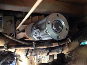
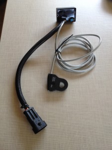
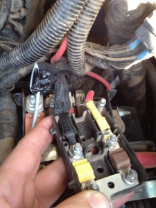
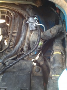
Most ABSs have an output that is activated when the ABS is actively controlling the braking and this signal is used to turn off the retarder during the ABS event. Unfortunately the Bosch 5.3 ABS does not have this output so I have built an electrical circuit to monitor the current; this circuit uses a hall-effect induction loop around the power cable going to the ABS. During normal operation, the ABS draws less than a couple of amps. But when its valves and pump activate during an ABS event, this current flow increases to between 10 and 60 amps! The circuit I have built detects this higher ABS event current flow and turns off the retarder until the ABS event is over. This circuit is powered from an ‘ignition on’ feed via a 5 amp fuse.
- ABS current monitoring circuit
- Feeding the ABS power cable through the current monitor sensor
- Monitor mounted behind the battery
Relay box wiring
Terminal V to indicator light to show retarder is working (I’m using the power level 4 light)
Terminal M to the earth terminal on the retarder (10 mm² cable)
Terminal 1 to hand controller position 1 output
Terminal 2 to hand controller position 2 output
Terminal 3 to hand controller position 3 output
Terminal 4 not used with this retarder
Terminal E to M terminal
Terminal + to battery via 175 amp fuse (35 mm² cable)
Terminal I to retarder terminal 1 (10 mm² cable)
Terminal II to retarder terminal 2 (10 mm² cable)
Terminal III to retarder terminal 3 (10 mm² cable)
Terminal IV not used with this retarder
Terminal S to brake relay coil (86) and the positive terminal of the buzzer
Retarder wiring
In addition to the connection to the relay box listed above I have connected the earth terminal to a chassis ground with 35 mm² cable.
Hand controller (HC) and power indicator wiring
The HC common terminal is connected to the Retarder Power output from the ABS current monitor circuit.
HC output 1 is wired to the relay box terminal 1 and the power indicator level 1 light
HC output 2 is wired to the relay box terminal 2 and the power indicator level 2 light
HC output 3 is wired to the relay box terminal 3 and the power indicator level 3 light
HC output 4 not used with this retarder. There is a small metal pin that can be put into the HC to limit the travel of the HC to 3 power positions as required for this retarder
Power indicator level 4 light is connect to the relay box terminal V
Power indicator common terminal is connected to ground
Buzzer
Positive terminal connected to the brake relay positive terminal (86)
Negative terminal to pin 4 of the 20 pin body builders connector
Brake relay
I install a relay (SPDT) into the brake pedal switch circuit so that the retarder will activate the brake lights and disconnect the cruise control. There are 4 wires going to the brake pedal switch and I wired them to the relay as follows:
a. The two green wires numbered 8879 are not connected to this relay.
b. The blue wire number 1176 is connected to the ‘normally open’ (87) terminal of the relay switch.
c. The green wire number 8158 is cut and:-
(i) the end from the switch goes to the ‘normally closed’ (87A) terminal of the relay switch.
(ii) the other end goes to the ‘common’ (30) terminal of the relay switch.
With this configuration, energising the relay has the same electrical effect as pressing the brake pedal. It does not matter if the brake pedal is pressed while the relay is energized or vice versa. The coil of this relay (85) is connected to ground and (86) to the terminal marked ‘S’ in the relay box and the positive terminal of the buzzer. The relay should be mounted vertically so that any bumps while driving do not move the de-energised relay contacts as this would lead to the brake lights flashing and the cruise control to trip out.
Testing the Telma Retarder
To ensure the installation is safe and functional I carried out the following testing. Note that most of the testing was done with the half gear in neutral so that the full loads could be applied to the transfer gearbox and retarder connection without the vehicle in motion.
1. ABS Interface
a. Connect Iveco EASY and enter the ABS testing function.
b. Turn on the retarder and check indicator lights are on.
c. Test each wheel’s ABS function in turn using the Iveco EASY. During the test the retarder should be turned off and the indicator lights go out. When the test finishes, the retarder should be powered back on and the indicator lights should come back on again.
2. PTO oil level
a. Run engine in 1st gear with the half gear in neutral.
b. Video the oil level through sight glass.
c. Note any level drop as the PTO section is filled with oil from the gearbox’s internal oil pump.
d. Turn off engine and see if the oil level recovers.
e. Top up transfer gearbox oil as required.
3. Retarder Electrical
a. Do a full resistance check on the retarder.
b. Monitor the retarder earth current during static operation of the retarder through braking levels 1, 2 and 3 (with engine in neutral and idling).
c. Monitor the voltage drop at the retarder during static operation of the retarder through braking levels 1, 2 and 3 (with engine in neutral and idling).
d. Check the brake lights illuminate when the retarder is selected.
e. Check the retarder power level lights indicate correctly on the dashboard.
4. Physical installation
a. Run the engine in 1st gear with the half gear in neutral.
b. Video the retarder and transfer gearbox, looking at the mountings’ deflections.
c. Hold 1500 rpm on the engine.
d. Progressively select retarder stages – checking the structures at each stage.
e. Select 2nd gear and repeat items c & d above.
f. Select 3rd gear and repeat items c & d above.
g. Select 4th gear and repeat items c & d above.
h. Select 5th gear and repeat items c & d above.
i. Finally increase engine rpm, in 5th gear with stage 3 retarder engaged, to 3200 rpm and check the structure is ok. This is equivalent to doing 110 kph (i.e 10% above the vehicle’s speed limiter setting of 100 kph) and is therefore above the maximum braking torque and Hp which the retarder will have to absorb during use.
5. Road test
a. Ensure everything is still secure.
b. Test the retarder at slow speed first stage.
c. Test the retarder at increasing speeds up to 100 kph with first stage.
d. Test the retarder at slow speed second stage.
e. Test the retarder at increasing speeds up to 100 kph with second stage.
f. Test the retarder at slow speed third stage.
g. Test the retarder at increasing speeds up to 100 kph with third stage.
6. Final inspection
a. Check all physical fixings for security.
b. Check all structures for cracking or signs of wear or rubbing.
Conclusion
The initial impression is that it will be great during hill descents and is also good for general slowing down at road junctions or in traffic which should help to reduce brake wear. It also keeps a smooth speed reduction while you are changing down through the gears. I think it will be good on steep off-road descents too. I will add a fuller report in a few weeks when I have more experience of driving with it.
Retarder Updates
Retarder Update No. 1
How is it going after 1,500 km with the retarder?
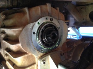
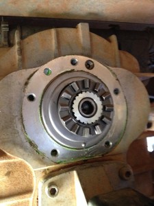
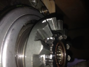
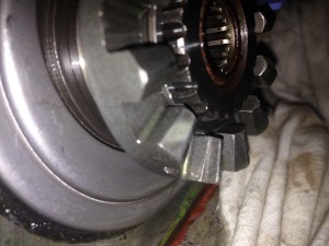
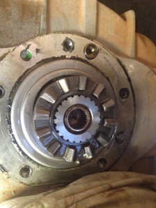
I removed the PTO so that I could do a few checks to: (i) ensure that the shims I installed in the PTO have set the engagement cogs at the correct spacing; and (ii) see if there is any excessive wear on these cogs. From the photos below you can see that the PTO looks like new: no wear visible on either side or on the ends of the teeth. This is very reassuring and indicates that the PTO is holding up well with the use of the retarder. Using an EASY, I also ran a test of the ABS sensing circuit: it is still working correctly and switching off the retarder during ABS activation.
- As you can see no wear after 1500km of use
Now that we are used to driving Cuthbert with his new retarder, what do we think of it?
Well, if you are looking for more powerful brakes that aren’t going to overheat, the retarder is not the answer. However, if you want to be able to control your speed on hill descents and significantly reduce the wear on your brakes, the retarder is ideal. Telma advertises that normal brake-life on a truck increases by 400% when their retarder is used. So far, we reckon that we have probably reduced our use of the brake pedal by around 70%, so it is certainly a significant reduction in brake-wear! When for example, we are slowing down towards a junction or, approaching slower traffic on a motorway, we simply apply the retarder and only use the foot brake at the final stages of a stop to come to a standstill. The retarder’s action is very smooth and controllable with the 3 stages of braking.
On down-hill runs it is very good for controlling speed, and while changing down through the gears it remains engaged keeping the speed under control. So far, have only been on hills on English roads (nowhere near as dramatic as the serious gradients that we will encounter when we get to the Andes!) and only a couple of them had a stated gradient.
On a 12% hill at approx. 5,800kg, we maintained comfortably a speed of 40 mph (64 kph) in 4th gear with the 2nd stage of the retarder engaged; the retarder’s 3rd stage then slowed us down without using the brake pedal. On a 15% hill also at approx. 5,800kg, we used the 3rd stage of the retarder to maintain our speed. In both of these descents I could have engaged a lower gear to assist the retarder, but it handled the task well with the engine at very low rpms.
In summary: hill descents are no longer the horrible experience they once were. Cuthbert can now descend under control, without the engine having to be held at high revs to maintain the speed. This allows us to travel at the speed of the surrounding traffic so that: (i) there is a much lower chance of vehicles running into the back of us; and (ii) the normal brakes are kept cool ready for any emergency use. I am confident that on the much steeper slopes, the combination of a lower gear and the retarder will provide a comfortable descent without the use of the foot brake and it will also be great on off-road tracks.
Retarder Update No.2 – Jan 2016
The retarder is connected through the transfer gearbox and so it’s braking power is split to the front and rear axle by the centre differential. This centre differential has a torque split of 68% to the rear axle and 32% to the front axle. Therefore, the retarder’s braking is also split 68%/32% between the two axles. This is a great improvement over the normal retarder installations where the retarder is only connected to the rear axle. However, during steep descents on loose or slippery surfaces (mud, gravel etc) with the retarder on maximum, I have found that if I use the foot brake gently to reduce speed for a corner, it can cause a rear wheel to lock-up.
This rear wheel lock-up triggers the activation of the ABS. The ABS activation turns off the retarder and, as the foot brake is only lightly pressed, this leads to a sudden acceleration. This is a very unpleasant experience, but it at least proves that my ABS interface works correctly. To deal with this, I now use the centre differential lock for steep descents on loose or slippery surfaces. With the centre differential locked, the retarder’s braking force is now applied 50%/50% to the front and rear axles and the ABS is disabled (a function of the centre differential lock), so I no longer experience the rear wheel lock-up or retarder deactivation by the ABS.
I have also tried using the retarder while off-road and in low range. The low range has a ratio of over 3:1 which makes the retarder over 3 times more powerful! This is great for descending very steep slopes as the speed can be accurately and powerfully controlled with the retarder.
I installed the retarder at 54,720 km. At the same time, I replaced the front brake pads which had come to the end of their life. Up to that point, the front pads had worn down from 15 mm of braking material to 2 mm (the minimum). This means I had covered 4,209 km for every 1 mm of braking material used. Since installing the retarder and new brake pads, I have travelled 22,553 km. The new pads have worn down from 15 mm to only 13 mm, so I have covered 11,276 km for every 1 mm of braking material used. That is a brake pad life extension of 268%! Rather than replacing the pads every 55,000 km, I will now only need to replace them every 146,000 km!
Retarder Update No.3 – Jul 2016
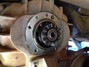
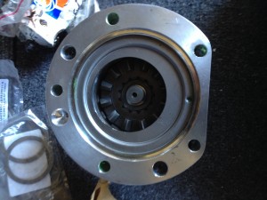
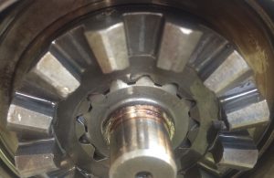
I decided to check the wear of the PTO teeth now that we have driven over 42,000 km with the retarder installed. As you can see from the photo below there is very little wear. I am happy this installation is not overloading any of the transmission components.
Retarder Update No.4 – 23 Dec 16
The truck has now done a total of 112,260 km, which is 57,540 km since installing the retarder. The brake pads fitted at the same time as the retarder have now only worn down from 15 mm to 10.4 mm. Comparing this wear to the wear on the original brake pads (before the retarder was fitted), there has been an increase in brake life of 297%! The distance driven per 1 mm of brake pad wear has increased from 4,209 km to 12,509 km. Put another way, my brakes now last 3 times as long – a very significant increase. I will not be fully recovering the cost of the retarder installation any time soon. Nevertheless, it’s nice to have a reduction in servicing costs as well as the added safety the retarder provides.
Retarder Update No.5 – 1 Mar 17
A few paragraphs above I mention that “I have also tried using the retarder while off-road and in low range. The low range has a ratio of over 3:1 which makes the retarder over 3 times more powerful! This is great for descending very steep slopes as the speed can be very accurately and powerfully controlled with the retarder.” I have now done the maths on the increased Retarder braking force due to the gear ratios in the transfer gearbox:
– In high range, I get the retarder’s rated 350 Nm, with the half gear selected this increases to 435 Nm and is what I use on most steep ‘on-road’ hills.
– In low range, there is a very large increase to 1090 Nm and in low range with the half gear selected, it becomes a massive 1357 Nm; serious stopping power!
Retarder Update No.6 – 21 Dec 18
A number of people have contacted me requesting the part numbers for the Iveco parts. These are the part numbers I used, but Iveco may have updated them. An Iveco garage or www.vexi.co.uk should be able to find you the new part numbers using these old ones.
Power Take-Off unit: 504276738 (£2173 vexi price 21 Dec 18)
Propeller-shaft: 5801549827 (£535 vexi price 21 Dec 18)
Propeller-shaft nut: 17309031 (4 required) (£0.68 vexi price each 21 Dec 18)
Propeller-shaft bolt: 8600231 (4 required) (£2.33 vexi price each 21 Dec 18)
Note, the retarder was supplied with studs and nuts for the propeller-shaft at the retarder end.

