
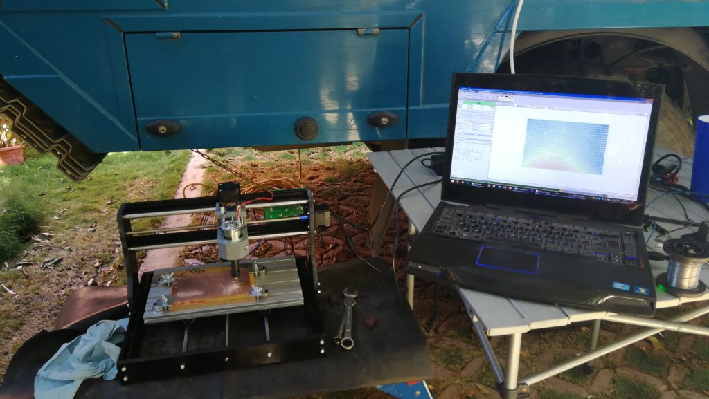
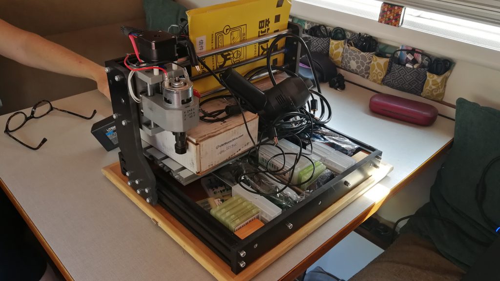
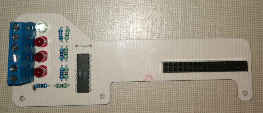
I like to mess around with electronics and have built a few projects for Cuthbert. To start with, I used Vero-board to build the circuits, but I’ve always liked the idea of making my own Printed Circuit Boards (PCBs). While we were parked up in Overland Oasis waiting for our new windscreen, I decided to buy a small Computer Numerical Control (CNC) milling machine. It’s a SainSmart Genmitsu CNC ROUTER 3018-PRO from China with the optional laser; quite a cheap machine but I’ve been able to get some great results.
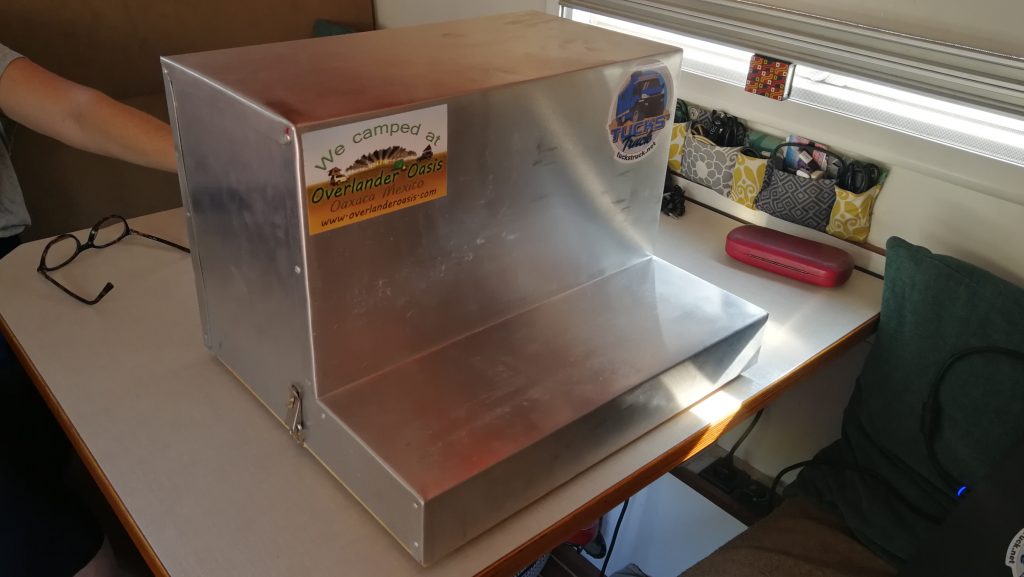
Calvin at Overland Oasis is a great mechanic and fabricator and has made this rather nice baseboard and case for my CNC milling machine. Thanks Calvin! In this I can store the power supply, laser and all the cutting bits and accessories, making it much easier to stash in the back of the truck.
I’m not going to write an instruction manual for how to use it for making PCBs, there are loads of websites and YouTube videos covering the subject. But here’s a very quick overview of the process…
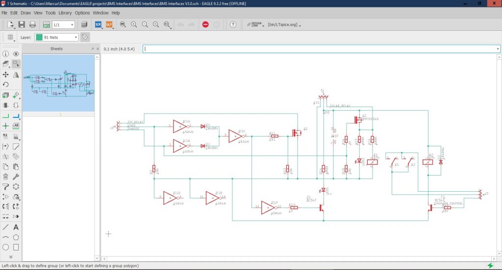
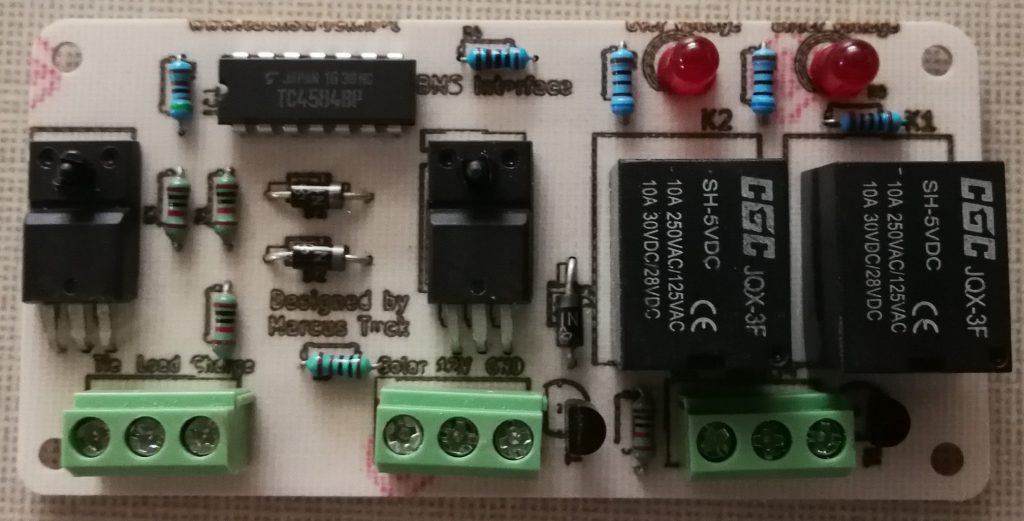
I start by designing my circuits in Eagle, a free CAD program designed for electronics. Once I have ‘built’ the circuit, I can lay-out the components on the PCB and join all the tracks.
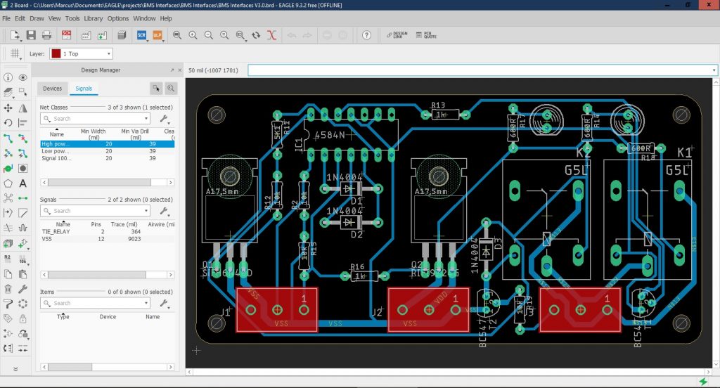
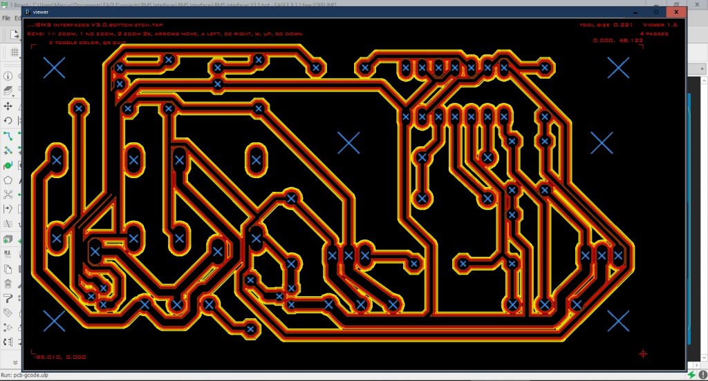
I then have a couple of options to convert this design into a file that can drive the CNC. I can either: (a) use the User Language Program ULP called ‘pcb-gcode’ loaded into Eagle that can produce the CNC files;
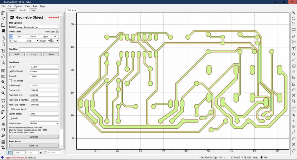
or (b) export the Eagle files into FlatCAM and process them into CNC files.
Whichever process I use, I import the CNC files into bCNC to control the CNC milling machine.
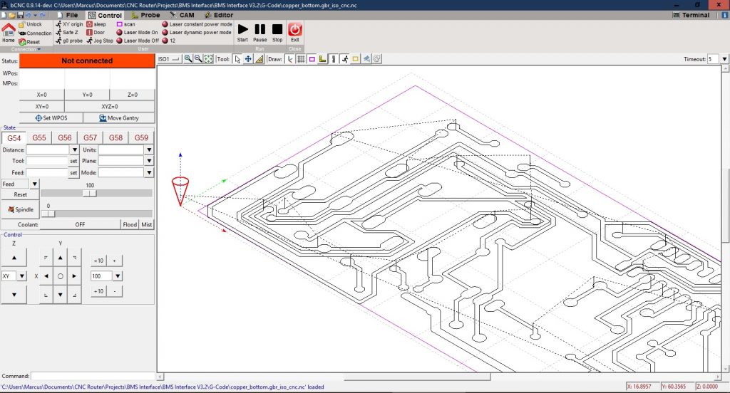
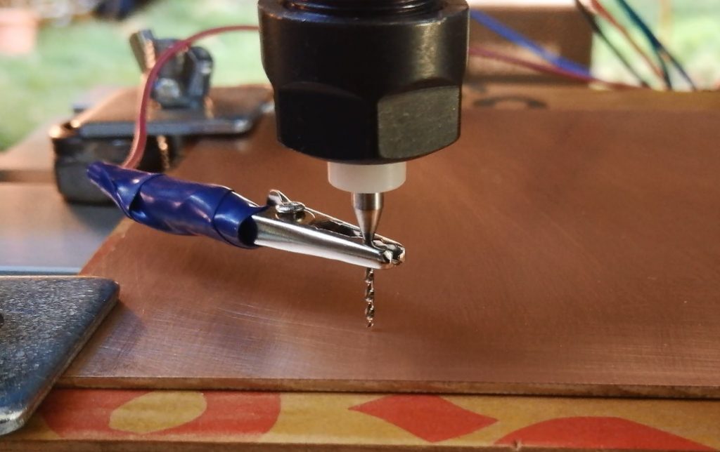
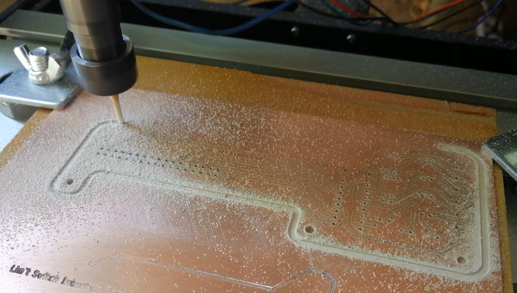
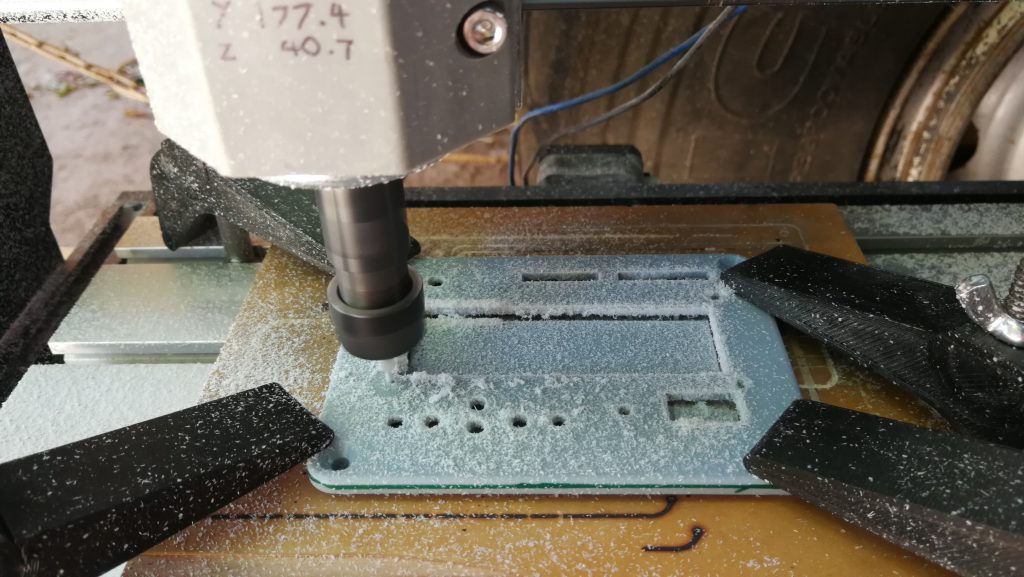
One problem that sometimes happens when milling a PCB to a depth of only 0.09 mm, is that a slight bend or twist in the PCB can seriously affect the cutting depth. bCNC has a great feature that allows it to ‘probe’ the surface of the PCB making exact measurements of the PCB’s actual height from a datum. bCNC can then apply this data to the CNC files and adjust the milling depth across the PCB to compensate for any imperfections. The probing works by attaching a wire to a drill bit and a return wire to the PCB. bCNC then drives down the drill bit until the electrical circuit is made. The height of the drill bit is recorded and then moved to a new position and the procedure is repeated.
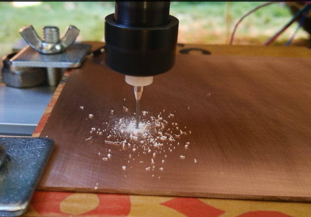
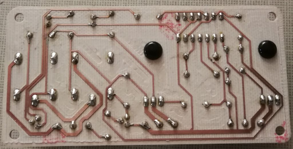
The basic procedure for creating a PCB starts by drilling all the holes.
Next milling the gaps between tracks.
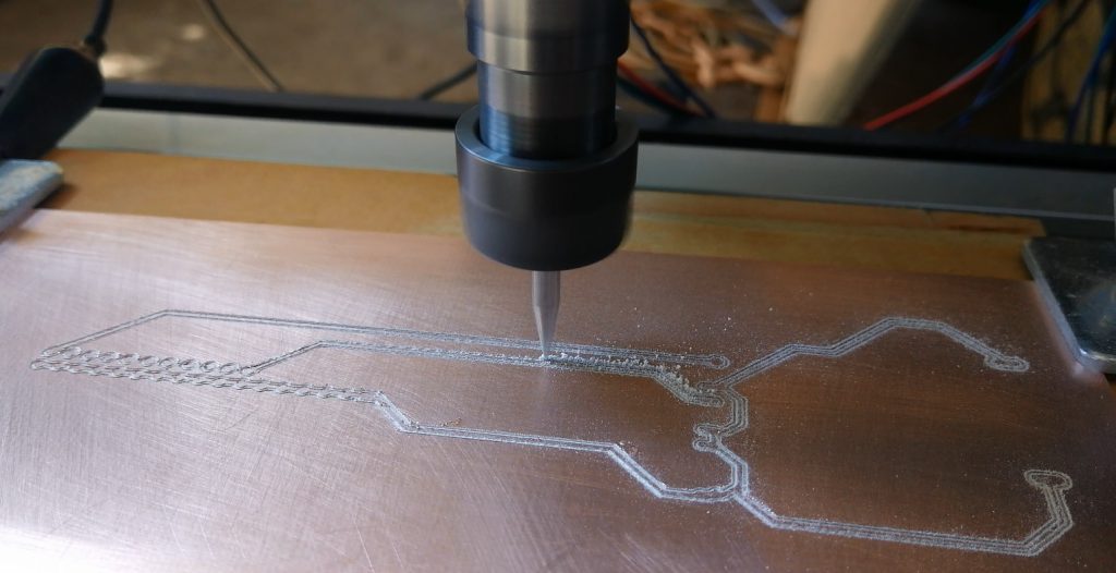
You can cutout the minimum clearance between the tracks or remove all of the copper you don’t want (but this is a much longer process).
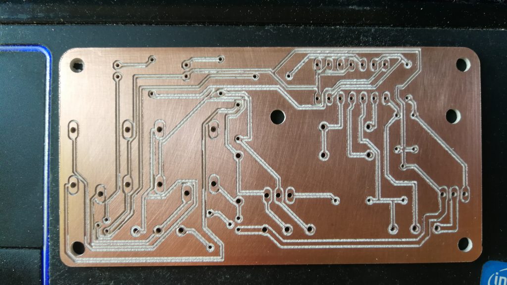
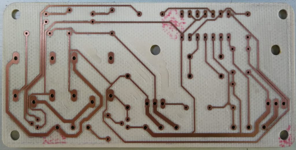
Then the PCB is cut out.
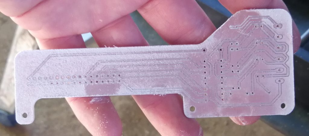
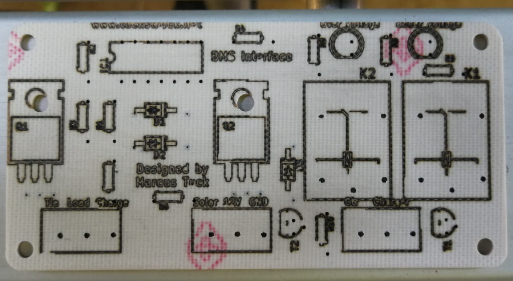
I can also use the laser to write on the back of the PCBs.
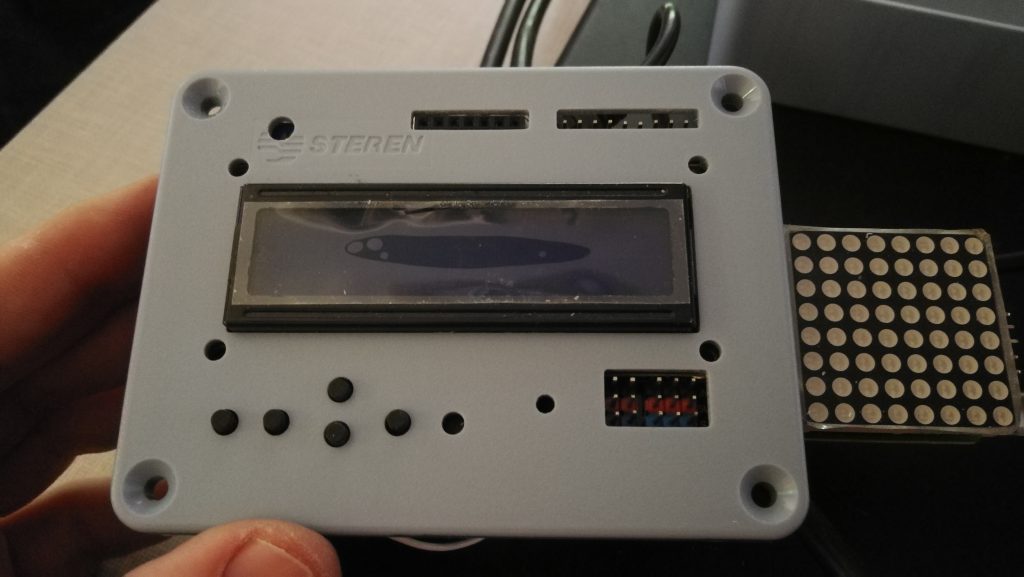
The CNC milling machine is also very good for cutting precise holes in plastic boxes for mounting projects.
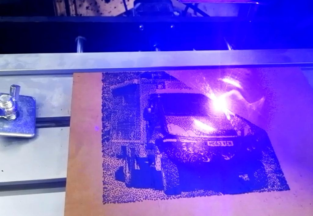
The laser can also be used for burning pictures into wood.
I’m sure I will find many more uses for this great ‘toy’ over the years….