
If you’re a geek like me, there are several reasons why you might want to replace the standard router issued by Starlink. To replace the router, you’ll need a POE (Power Over Ethernet) Injector. You can also use a POE Injector if you want to run the Starlink dish on DC power rather than AC (running the dish on DC rather than through an inverter while off grid can reduce the power consumption by as much as 40%! See my DC conversions here).
POE injectors are common devices that are readily available to buy. However, Starlink does not follow the conventional POE configuration, and this can complicate the use of a standard POE Injector. The round Dish uses T-568B configuration for its dish ethernet cable. The rectangular Dish uses a different connector, but the signals to colour codes of the cables are the same. For example: a cable from a rectangular Dish, fitted with a shielded RJ45 connector wired to T-568B can be plugged into and powered from a round Dish power supply.
Development
I tested the output of the round Dish power supply and found the following on the ethernet cable/RJ45:
- Pin 1, data B+ = white with orange stripe
- Pin 2, data B- = orange
- Pin 3, data A+ = white with green stripe
- Pin 4, data C+ = blue
- Pin 5, data C- = white with blue stripe
- Pin 6, data A- = green
- Pin 7, data D+ = white with brown stripe
- Pin 8, data D- = brown
The positive power is supplied on data A and data B signal pairs. The negative is on data C and data D signal pairs.
Note that the normal convention is data A and data C signal pairs are positive and data B and data D signal pairs are negative. Obviously, the Dish RJ45 plug could be wired differently to T-568B colour code to make it work. But the device plugged into the other side of the POE injector would also need to be rewired from standard to get the data on the correct wires. This could lead to confusion and require special cables to be made. I decided it would be better to have a configuration that would allow routers or other devices to plug in directly without requiring special cables.
The DC power is applied to the data signals through a pulse transformer. I chose to use the same pulse transformer that Starlink have used in the round Dish power supply to ensure compatibility.
The circuit is quite straightforward, but there can be complications with the signals due to the layout of the PCB. My testing below shows that my design works and does not ‘speed limit’ the data.
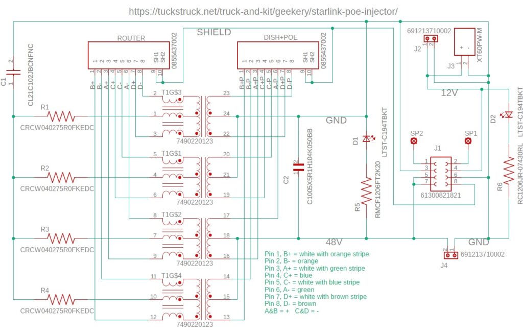
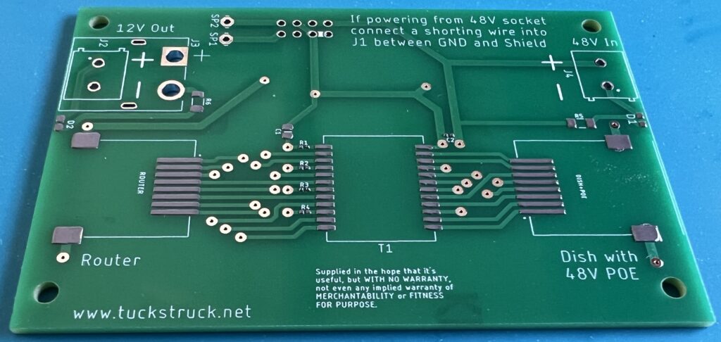
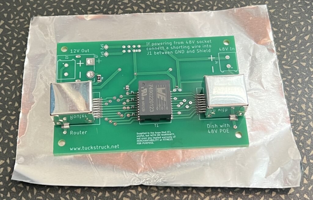
The PCB is designed so that J1 can plug onto the Starlink mains power supply. It can also be used with another 48 V power supply by connecting it to J4, this is a good way to do a DC conversion.
Connector J2/J3 is a 12 V output from the Starlink power supply and can be used to power a router or switch. Note the Starlink power supply has a maximum 12 V current of 1.25 A.
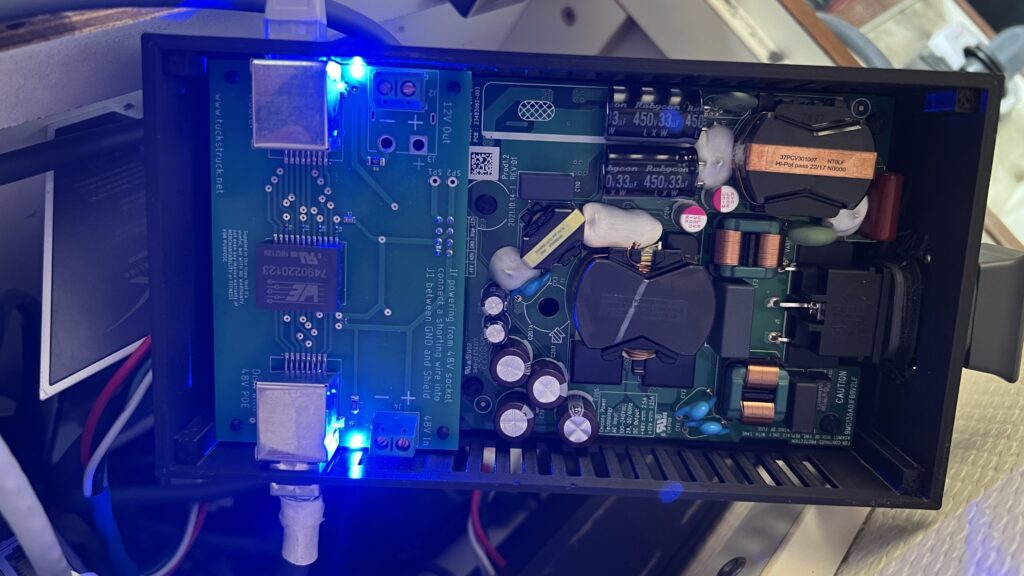
D1 will light when there is 48 V on the PCB from a connected power supply.
D2 will light when there is 12 V on the PCB from the Starlink power supply.
I had a simple case made by 3D printing. It’s not a great design for long term use but was ok for testing.
Prototype PCB Specification
The prototype was built on a 1.6 mm thick FR-4 TG130 PCB with 1oz copper layers and HASL (Hot Air Solder Level) solder pads.
Testing
These are the tests I performed:
1. I put the POE injector, unpowered, between the Starlink router ethernet adapter and my laptop computer. I then ran a few speed tests to confirm it was working correctly.
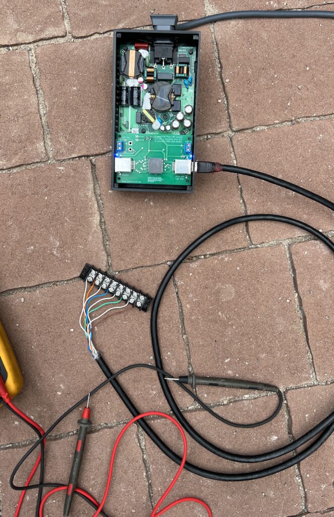
2. I attached the POE injector board to the Starlink rectangular Dish router power supply (that I have removed from my router). I used a breakout cable to check the voltages and wiring for the POE output for the dish side.
3. I connected the Dish and a 3rd party router to the POE injector and ran more speed tests and checked the debug data ‘SlowEthernetSpeeds’ was ‘false’.
4. I monitored the temperature of the Starlink power supply to ensure it did not overheat as it had no heatsink.
Results
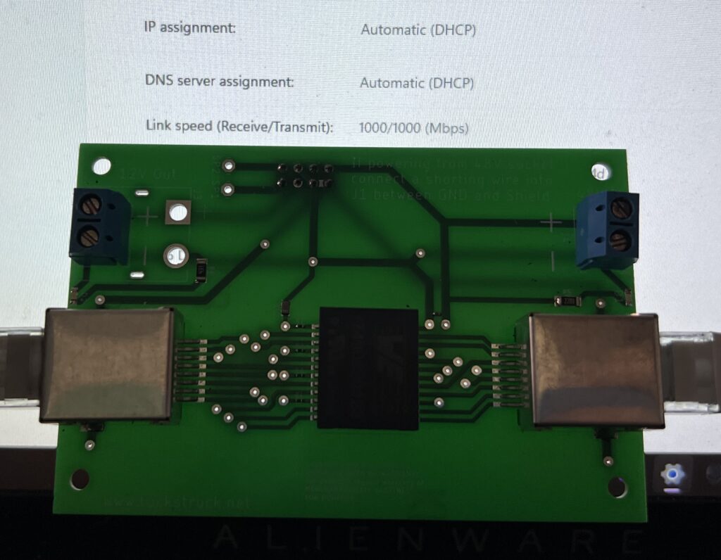
The POE injector was able to acheive a Link speed of 1000/1000 (Mbs) – a gigabit connection. This was an unpowered test connected between a laptop and the ethernet adapter on the Starlink router. This shows that the POE injector should not have any data speed limitations.
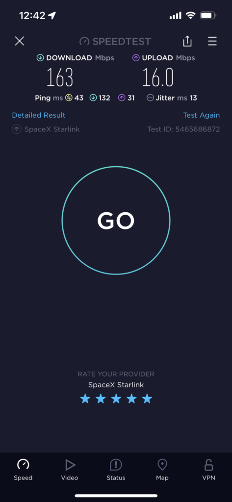
I performed several tests and regularly achieved download speeds in excess of 100 Mbs (these were Starlink speed tests, not pure ethernet speed tests). This was significant as many who have tried to use POE injectors were unable to reach 100 Mbs. My highest speeds were 163 Mbs down and 16 Mbs up. I ran the Starlink mains power supply for 4 hours and 20 minutes without any heatsinks attached, but air could circulate around the power supply. The ambient temperature was 28°C and the hottest temperature I recorded on the Starlink power supply was 60°C, well within the component’s specifications. These results are for a Standard rectangular Dish with the snow melt turned off. I have not been able to test with snow melt on as it is too warm in my location.
Availability
As we are travelling full time it is impractical for me to start to manufacture these units. However, I am providing all the information you need to make one yourself or have someone else make one for you. I am not going to charge for any of the information. I am not a professional electronics engineer and this is therefore a ‘use at your own risk’ option.
The PCB can be ordered from Seeed Studio here or if you want to order the PCB from another supplier I have uploaded the Gerber files to my Dropbox here.
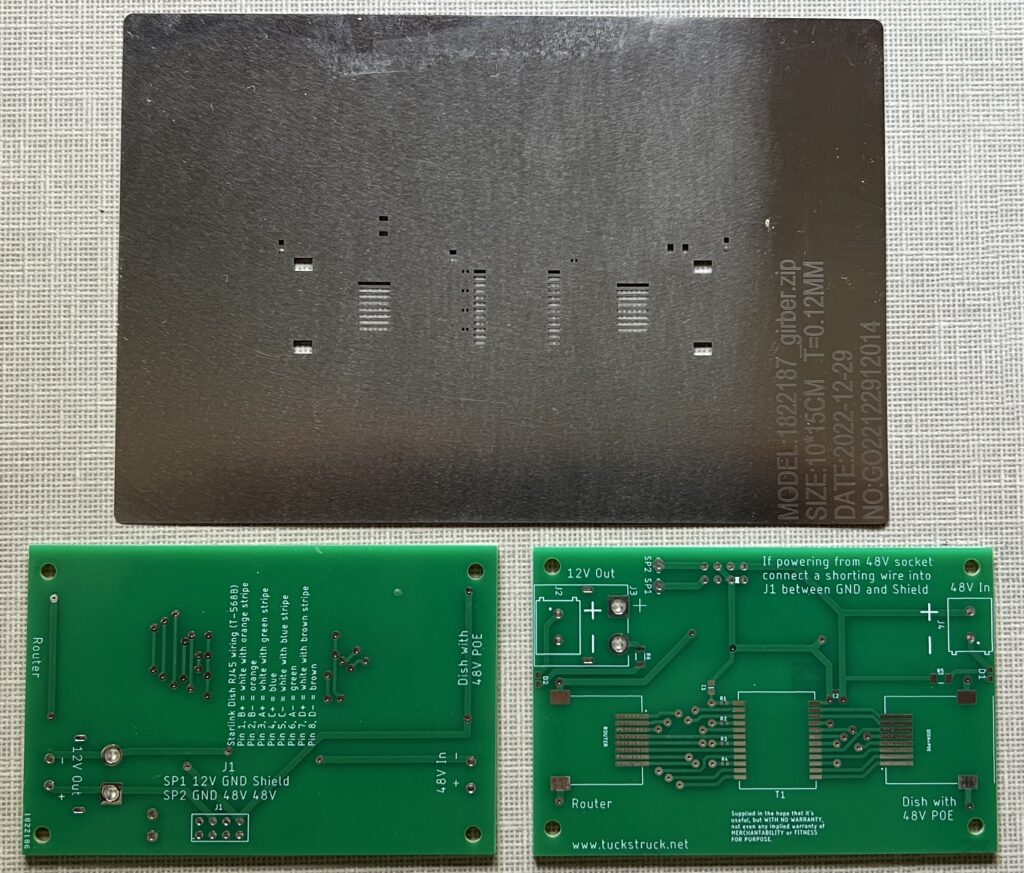
If you want to use a stencil to assist with applying solder paste, these are the settings I used on Seeedstudio for this PCB:
- PCB Dimensions – 10.0cm * 15.0cm Frameless – eff.8*13
- Sides – Top only
- Stencil quantity – 1
- Fiducial Mark – No fiducial
- Thickness – 0.12 mm
- Polishing Technique – Polished
The Zipped Gerber file required for the stencil is the same as the one used for the PCB. You can download this from the gallery page and then load it into the stencil ‘Add Gerber File’ box.
Note: I don’t make money from the PCB sales from Seeedstudio, they’re just the company I used to make the PCB for me. Follow the link above, scroll down to the bottom of the page and you can download the Girber files in a Zip file, which can be used by any PCB company to produce these boards for you.
Here is the Bill Of Materials (BOM) where the components can be ordered: https://www.digikey.com.mx/en/mylists/list/W35L1GE63K
This is on the Digikey Mexico website but they can supply from Digikey in other countries too (the Mexico website actually ships from the US).
The customer reference in the BOM ties up with the circuit diagram and PCB for the component. This should be printed on the component packets when you receive them to make construction easier.
- If you do not need the LEDs you can delete D1, D2, R5 and R6.
- If you are not going to plug it onto the Starlink power supply you can delete J1.
- If you don’t need the screw terminals for 48V you can delete J4.
- If you don’t need the screw terminals for 12V you can delete J2.
The PCB has been designed to take an XT-60PW-F plug for the 12V output at J3 instead of a screw terminal (J2) if required (Digikey do not stock them).
Assembly
WARNING: Mains AC and 48V DC are dangerous voltages and the power supply can store energy for a long time after it has been disconnected from the mains power. Do not attempt to use this POE injector if you are not sure about what you are doing.
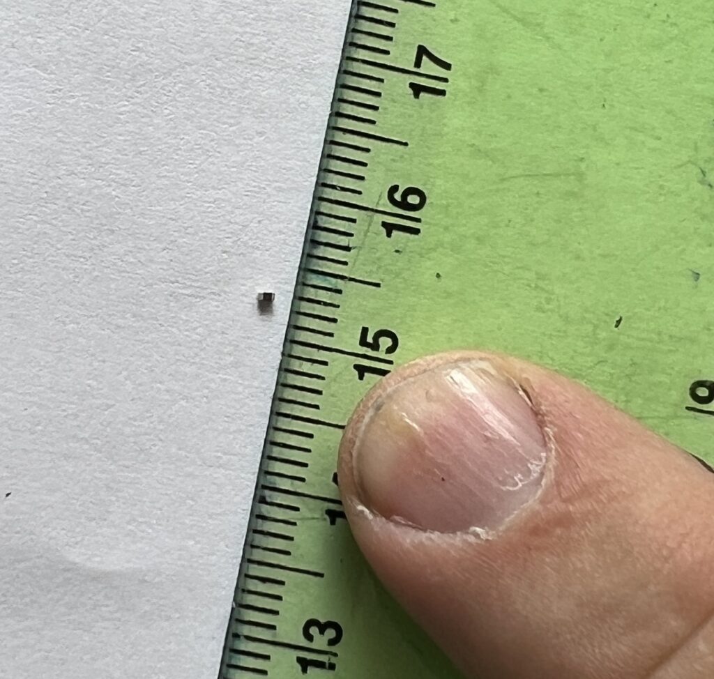
The PCB is not too complicated but some of the components are very small, 1 mm x 0.5 mm. It could be manually soldered. However, I used a stencil to help apply solder paste to the PCB, also available from Seeed Studio (see link above). The solder paste I used was ‘solder paste no clean 63SN/37PB’: https://www.digikey.com.mx/en/products/detail/chip-quik-inc/SMD291AXT5/8543522?s=N4IgTCBcDaIMoFkAiYCcBGAggDQCoFYBaAOSRAF0BfIA
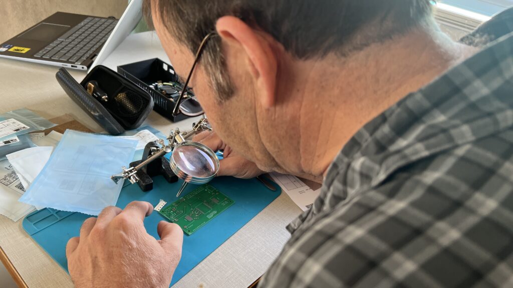
After applying the solder paste, I positioned all the surface mount components on the board, starting with the smallest.
The two LEDs need to be installed the correct way around, Anode to + and Cathode to -. The top of the LED has a small stripe on the Cathode – end, see data sheet: https://optoelectronics.liteon.com/upload/download/DS22-2010-0025/LTST-C194TBKT.PDF
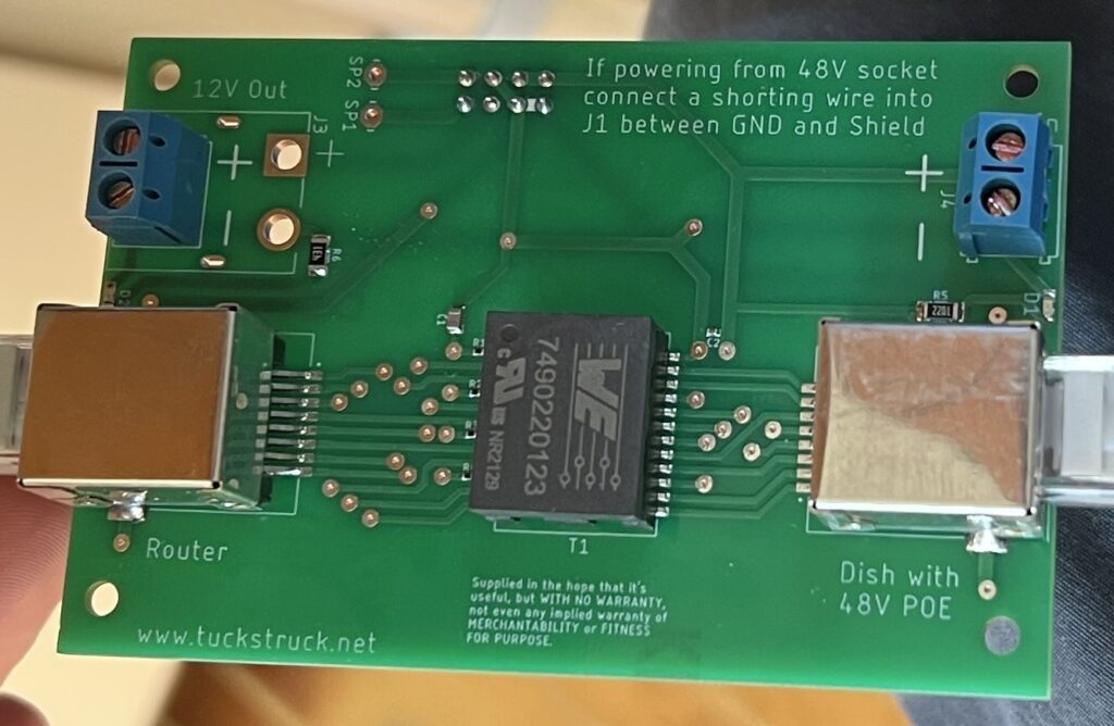
For D1 the side going to J4 is the Cathode – and for D2 the side going to J2 is the Anode +. The pulse transformer T1 should be installed with the round dot on top of the case at the opposite end to the T1 marking on the PCB.
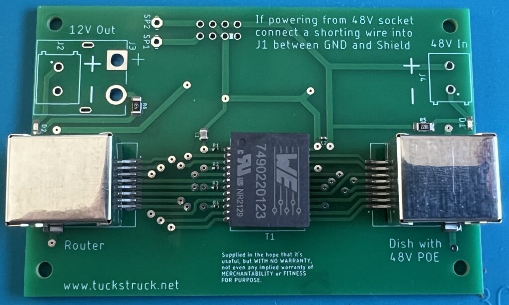
With all the surface mount components fitted I heated the PCB in a frying pan (a small piece of aluminium foil under the PCB to protect the frying pan). I tried to replicate the heat profile recommended by the solder paste manufacturer by adjusting the heat while monitoring the temperature using an IR temperature sensor. The temperature profile is on a card included with the solder paste or can be seen in the data sheet: http://www.chipquik.com/datasheets/SMD291AXT5.pdf
Once the solder had melted and flowed, I removed the PCB from the frying pan and left it to cool.
The RJ45 sockets case feet did not solder in this process as the case was acting as a large heatsink. These feet were easily manually soldered. Next, I installed the through hole components, the plug and screw terminals.
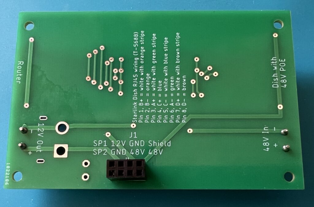
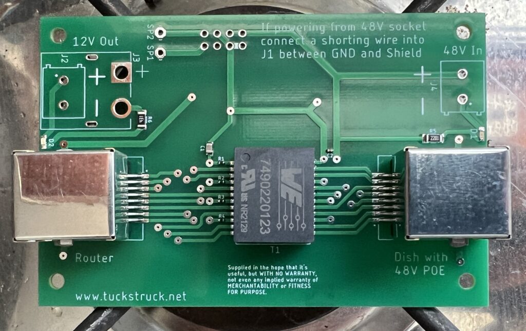
If you are not using the Starlink power supply to provide power, you will need to add a small link wire between GND and Shield pins of J1. There is a printed white line between the two pins that need to be connected together. This is to connect the shield to the negative supply.
The dish is plugged into the RJ45 socket labelled ‘Dish with 48V POE’. The Dish cable should be wired to T-568B colour code, it is printed on the back of the PCB for your convenience.
Your router is plugged into the RJ45 socket labelled ‘Router’.
If you sign up for Starlink with our referral code (click here), we will each receive one month of free service 30 days after activation. For more information on how it works, check out Starlink support topics here.