
So how much does your truck weigh? Most overlanders know they shouldn’t overload their vehicle. Prolonged overloading leads to excessive strain/stress on the vehicle, which inevitably leads to premature wearing of parts and likely breakdown if not kept in check. But without access to a weigh-station, it can be hard to know how much the vehicle weighs. Even if you check it at at weigh-station before setting off, wouldn’t it be nice to see how the weight has changed after adding/removing bits and pieces over years on the road?
I decided to make a small, portable weigh-system so I can check our vehicle’s weight easily whilst travelling.
The hardware
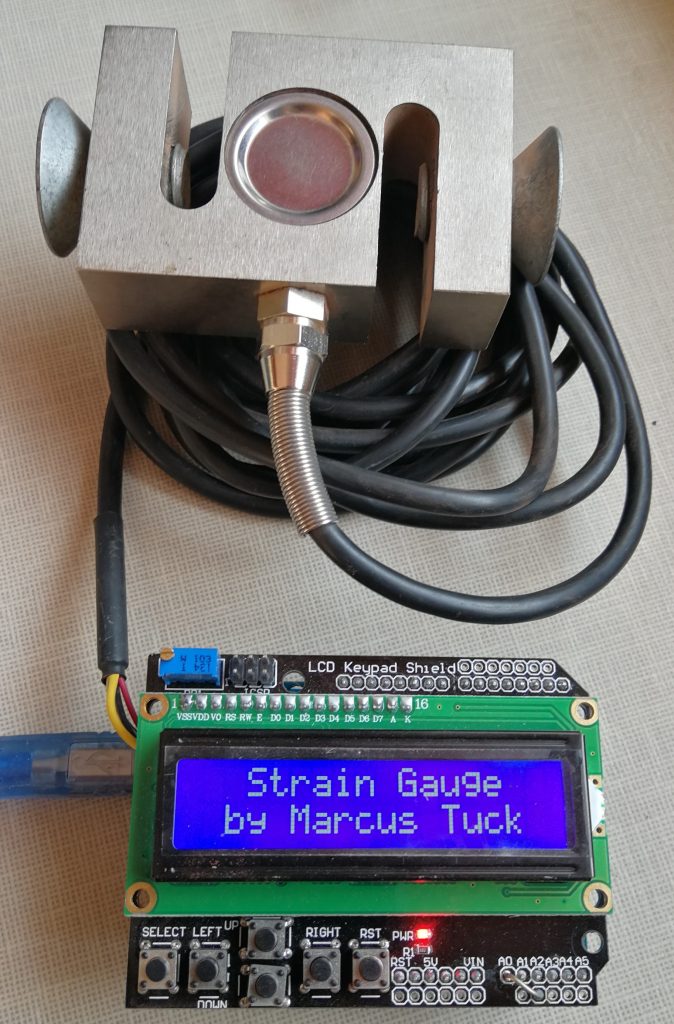
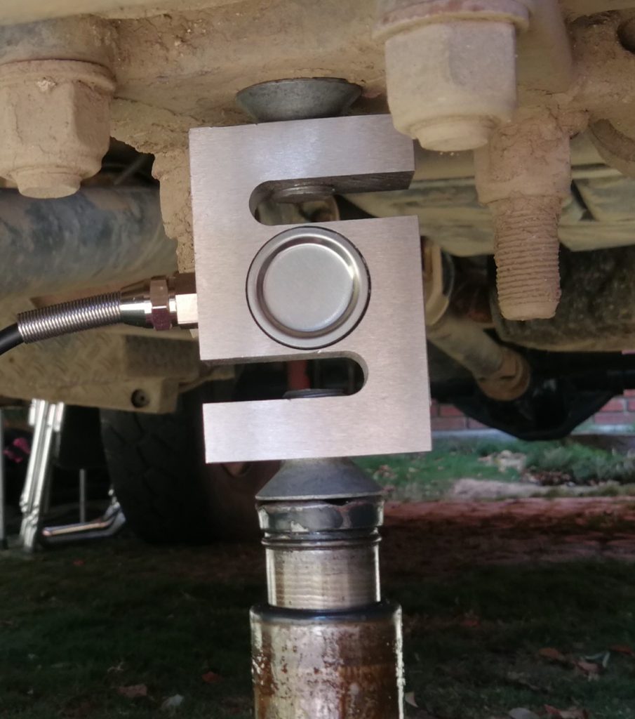
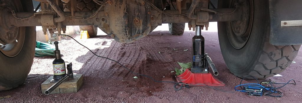
I bought a ‘PSD-S1 Load Cell’ by Pushton in China (Amazon, £21.50). This strain gauge has a capacity of 2000 kg and is ideal for my application. I have inserted a couple of tapered screws/bolts to make jacking pads and install the strain gauge between the jack and the axle.
I have already used Arduino computer modules for various projects, so this was the logical platform for me to use in this project. If you haven’t used an Arduino before, I would recommend that you get a starter kit. The kit comes with instructions, plus there are also loads of on-line resources and guides. For this particular project, I used an Arduino Uno.
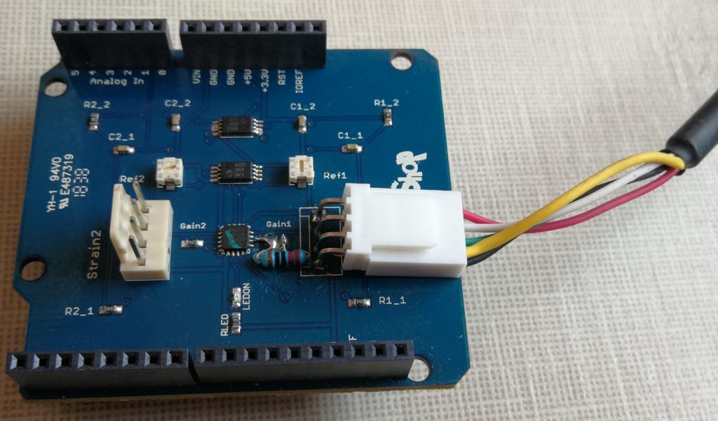
To interface the strain gauge to the Arduino, I used a Robot Shop Strain Gauge/Instrument Shield: https://www.robotshop.com/en/strain-gauge-load-cell-amplifier-shield-2ch.html
To optimise the strain gauge shield I had to make a few modifications:
- I wanted to install an LCD keypad shield on top of the strain gauge shield, but the strain gauge connector would not allow another shield to be installed on top. I therefore replaced the vertical strain gauge connector with a 90 degree one for input 1.
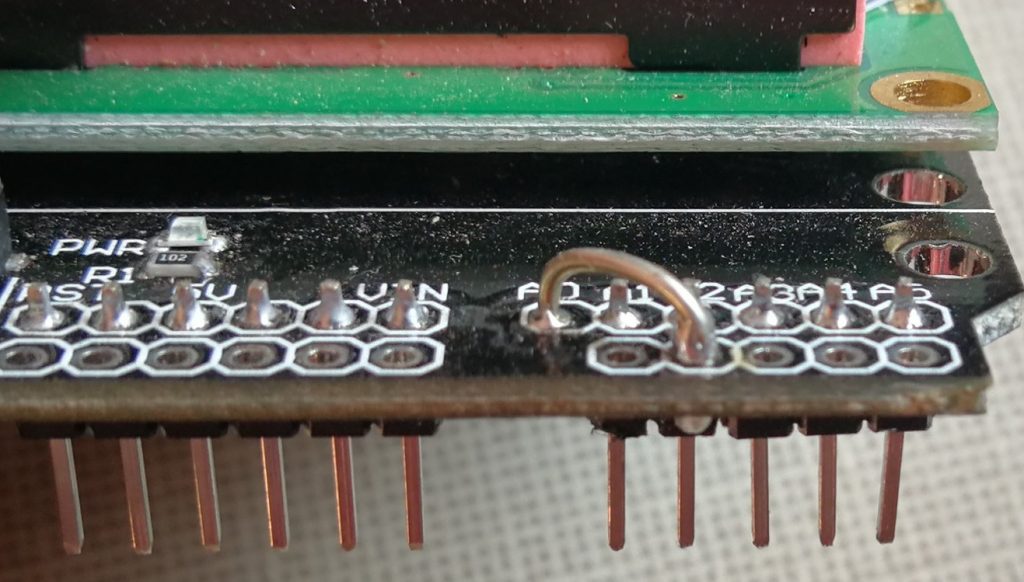
- The strain gauge amplifier and strain gauge have been wired to the 3.3V supply to make the shield compatible with the lower voltage Arduinos. However, I used a 5V Uno and wanted the maximum voltage readings available. I therefore cut the 3.3V pin from the shield, bent it over and soldered it to the 5V pin. This increased the supply voltage to the amplifier and to the strain gauge to 5V, giving the maximum output possible for the Uno.
- I also wanted to optimise the gain of the amplifier for this application. The strain gauge specifications show that it outputs 2mV/V at full load. This means that with a 5V supply and 2000 kg applied, the output voltage will be 10mV. As the amplifier is supplied with a single supply, the no-load output voltage will be 2.5V (which can deviate to 0V or 5V depending on whether the strain gauge is under tension or compression). The strain gauge shield is supplied with a 100Ω gain resistor, resulting in a gain of 495. This much gain would result in the amplifier being saturated (giving the maximum output) when a load of about 1000kg is applied. Using the gain equation in the data sheet for the AD8426 amplifier chip (gain = 1 – (49400 / R) ) I selected a 220Ω gain resistor which resulted in a gain of 226. This means that the amplifier output varies by 2.26V at 2000kg. Therefore, the input to the Uno will be in the range of 0.24V to 4.76V for a load of ±2000kg (this safely allows for a 10% overload and the readings to still be accurate). As the Uno analogue input has a 10 bit resolution and a voltage range of 0 to 5V, this means that each bit is equivalent 4.9mV. Given the above calculations, the resolution of the system is approximately 4.3 kg per bit.
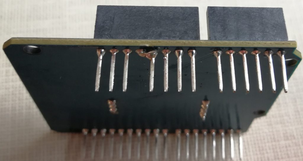
- On top of the strain gauge shield I installed an LCD keypad shield (there are lots of versions of these available to buy on-line). This again needed minor modification. The LCD keypad shield uses the A0 pin for the switches, but this is also the pin that is used by the strain gauge shield. I therefore cut the A0 pin from the LCD keypad shield and added a jumper wire between the A0 and A2 pins on this shield.
- The strain gauge wire colour coding is: Red +, Black -, Yellow cable screen, Green ‘+’ signal, White ‘-‘ signal. The strain gauge shield plug wiring: Pin 1 +, Pin 2 ‘+’ Signal, Pin 3 ‘-‘ Signal, Pin 4 Ground. However, to get a positive output with an increase in weight, the strain gauge signal outputs need to be reversed: red to pin 1, black and yellow to pin 4, green to pin 3, white to pin 2.
The software
I started with some basic code from:
https://www.robotshop.com/uk/strain-gauge-load-cell-amplifier-shield-2ch.html
I then re-wrote and modified the code for my application. The full code is listed at the bottom of the page. Please note I am not a software engineer, this is just me hacking around, so no guarantees of anything! If you choose to use it – it’s at your own risk!!
How I set-up and used this program:-
Setup:
- I connected to a laptop without the LCD shield installed and opened serial monitor at 115200 bps (note: the Ref1 control can’t be accessed with the LCD shield installed).
- I checked that a stream of data showing the analogue value and calculated weight was being received.
- I set the Ref1 resistor to obtain a raw analogue value of around 512 (± 10) with no load on the strain gauge.
- Finally, I installed the LCD keyboard shield.
Use:
- Select a side of the axle to weigh: FL = Front left, FR = Front right, RL = Rear left and RR = Rear right
- Use the up/down buttons to change between front and rear axles and left right buttons to change between sides
- On the top row, the ‘live’ weight is displayed
- The bottom row displays the total weight recorded and the maximum sensed for that measurement.
- Pressing ‘Select’ stores the value and adds it to the total. A * appears after the kg to show it is a stored value and now frozen.
- To delete this value, I press ‘Select’ again and the * disappears. The value is removed from the total and the readings become ‘live’ again.
- This above procedure is repeated for each axle position, until all 4 measurements are complete.
- It’s possible to scroll back to each of the stored measurements, which are displayed with a * after the kg.
Notes:
- To get an accurate reading, the vehicle should be on level ground with both sides of the axle jacked-up evenly.
- The strain gauge works under compression and tension, compression will result in a positive weight and tension a negative weight.
- Given the voltage and limitations of this configuration, the resolution is approximately ± 4.3 kg, so for the total vehicle weight approximately ± 17 kg.
So this is how I accurately weigh our vehicle, click here to see our vehicle Trim Sheet: https://tuckstruck.net/truck-and-kit/the-truck-technical-stuff/trim-sheet/
The software:
/* Strain Gauge Arduino Project

   Base code I used to start building this programme came from:-
   https://www.dfrobot.com/wiki/index.php/Arduino_LCD_KeyPad_Shield_(SKU:_DFR0009)#Example_use_of_LiquidCrystal_library
   https://www.robotshop.com/uk/strain-gauge-load-cell-amplifier-shield-2ch.html
   Notes:
         LCD module A0 pin was removed and a link wire added between A0 and A2 on the LCD shield was added to provide compatibility
         between the LCD shield and Strain Gauge shield

         Only stain gauge 1 is used

         The strain gauge shield was modified with a 90 degree connector to allow the strain gauge to be connected and the LCD shield
         installed over the top of the connection

         The strain gauge shield 3.3V leg was cut and soldered to the 5V leg

         The gain resistor (Gain1) for channel one was changed to 220Ω to reduce the channel one gain from 495 to 226.

         PSD-S1 strain gauge wire colour coding is: Red +, Black -, Yellow cable screen, Green signal +, White signal -
         Strain gauge shield strain gauge plug wiring: Pin 1 +, Pin 2 Signal +, Pin 3 Signal -, Pin 4 Ground
         However, to get a positive output with an increase in weight the PSD-S1 signal outputs need to be reversed:-
              red to pin 1
              black and yellow to pin 4
              green to pin 3
              white to pin 2

    How to use this program:-

    Setup:
    Connect to laptop without the LCD shield installed and open serial monitor at 115200 bps (note, you cannot access the Ref1 control with the LCD shield installed)
    Check you are receiving a stream of data showing the analogue value and calculated weight (mass).
    Set the Ref1 resistor to obtain a raw analogue value of around 512 (± 10) with no load on the strain gauge
    Now install the LCD shield

    Use:
    Select the side of the axle you are weighing, FL = Front left, FR = Front right, RL = Rear left and RR = Rear right
    Use the up/down buttons to change between front and rear axles and left right buttons to change between sides
    On the top row you will have the 'live' weight displayed
    On the bottom row you have the total weights recorded and the maximum sensed for that measurement
    Press 'Select' to store the value, and have it added to the total.  A * will appear after the kg to let you know it is now a stored value.
    If you want to delete this value, press 'Select' again and the * will disappear, the value will be removed from the total and the readings will become 'live' again.
    Move to the next axle position and repeat above procedure until all 4 measurements are complete.
    You can scroll back to each of the stored measurements and it will be displayed with a * after the kg.

    Note:
    The PSD-S1 strain gauge works under compression and also under tension, compression will result in a positive weight and tension a negative value
    Given the voltage and limitations of this configuration the resolution is approximately ± 4.3 kg so for the total vehicle weight approximately ± 17 kg

    Full write up of the project is on my website:- http://www.tuckstruck.net/truck-and-kit/the-truck-technical-stuff/strain-gauge/

*/

//********************************************** Calibration Adjustment data **********************************************************
float CalibrationValue = 4.32978;  // calculated value
//*************************************************************************************************************************************

#include <LiquidCrystal.h>
LiquidCrystal lcd(8, 9, 4, 5, 6, 7);

#define btnRIGHT  0
#define btnUP     1
#define btnDOWN   2
#define btnLEFT   3
#define btnSELECT 4
#define btnNONE   5

byte axle = 0;           // variable to store the axle position selection
byte side = 0;           // variable to store the axle side selection
byte store = 0;          // variable used in commanding a variable to be stored
byte lock = 0;           // variable used to lock the value displayed after it has been stored
int FL = 0;              // front left weight store
int FR = 0;              // front right weight store
int RL = 0;              // rear left weight store
int RR = 0;              // rear right weight store
int Max = 0;             // max reading
int CalibrationZero;     // used to store the zero calibration value
int newReading_Strain1;  // used to store the strain gauge readings
int load_Strain1;        // used to store the calculated load on the strain gauge
int time_step = 500;     // sets the time interval for taking strain gauge readings (in ms)
long time = 0;           // used in the time interval calculations

void setup() {
  Serial.begin(115200);
  lcd.begin(16, 2);
  lcd.setCursor(0, 0);
  lcd.print("  Strain Gauge");
  lcd.setCursor(0, 1);
  lcd.print(" by Marcus Tuck");
  delay(3000);                      // allows time for message to be read and the system to warm up ready for calibration
  lcd.clear();
  lcd.setCursor(0, 0);
  lcd.print("  Calibration");
  lcd.setCursor(0, 1);
  lcd.print("    no load...");
  delay(3000);                      // allows time for message to be read and the system to warm up ready for calibration
  CalibrationZero = analogRead(0);  // analogue in for Strain Gauge - zero calibration reading
  delay(100);
  CalibrationZero = analogRead(0) + CalibrationZero;
  delay(100);
  CalibrationZero = analogRead(0) + CalibrationZero;
  delay(100);
  CalibrationZero = analogRead(0) + CalibrationZero;
  CalibrationZero = CalibrationZero / 4;
  Serial.println();
  Serial.print("CalibrationZero = ");
  Serial.println(CalibrationZero);
  lcd.clear();
  lcd.setCursor(0, 0);
  lcd.print("  Calibration");
  lcd.setCursor(0, 1);
  lcd.print("   complete!");
  delay(2000);
}

void loop() {
  int lcd_key = read_LCD_buttons();  // read the buttons
  switch (lcd_key)                   // action depending on which button was pushed
  {
    case btnRIGHT:
      {
        side = 1;
        store = 0;
        lock = 0;
        Max = 0;
        break;
      }
    case btnLEFT:
      {
        side = 0;
        store = 0;
        lock = 0;
        Max = 0;
        break;
      }
    case btnUP:
      {
        axle = 0;
        store = 0;
        lock = 0;
        Max = 0;
        break;
      }
    case btnDOWN:
      {
        axle = 1;
        store = 0;
        lock = 0;
        Max = 0;
        break;
      }
    case btnSELECT:
      {
        store = 1;
        break;
      }
    case btnNONE:
      {
        break;
      }
  }
  if (millis() > time_step + time) {
    if (lock == 0) {
      newReading_Strain1 = analogRead(0) - CalibrationZero;                      // analogue in for Strain Gauge
      delay(100);
      newReading_Strain1 = newReading_Strain1 + analogRead(0) - CalibrationZero;
      delay(100);
      newReading_Strain1 = newReading_Strain1 + analogRead(0) - CalibrationZero;
      delay(100);
      newReading_Strain1 = newReading_Strain1 + analogRead(0) - CalibrationZero;
      newReading_Strain1 = newReading_Strain1 / 4;                               // averaged the 4 readings
      load_Strain1 = CalibrationValue * newReading_Strain1;
      Serial.print(newReading_Strain1 + CalibrationZero);                        // output data to laptop for calibration
      Serial.print(" raw analogue - adjust trim to approx 512, ");
      Serial.print(newReading_Strain1);
      Serial.print(" corrected analogue reading, calculated load = ");
      Serial.print(load_Strain1);
      Serial.println("kg");
      if ((load_Strain1 > 0) && (load_Strain1 > Max)) Max = load_Strain1;        // sets the max posative value
      if ((load_Strain1 < 0) && (load_Strain1 < Max)) Max = load_Strain1;        // sets the max negative value
    }
    lcd.clear();
    lcd.setCursor(0, 0);
    if (axle == 0) {
      lcd.print("F");
    } else {
      lcd.print("R");
    }
    if (side == 0) {
      lcd.print("L");
    } else {
      lcd.print("R");
    }
    if ((axle == 0) && (side == 0) && (FL != 0) && (store == 0)) {  // if a value has been stored it is displayed rather than live data
      lock = 1;
      DisplayInt(3, 0, FL);
      lcd.print("*");
    }
    if ((axle == 0) && (side == 1) && (FR != 0) && (store == 0)) {  // if a value has been stored it is displayed rather than live data
      lock = 1;
      DisplayInt(3, 0, FR);
      lcd.print("*");
    }
    if ((axle == 1) && (side == 0) && (RL != 0) && (store == 0)) {  // if a value has been stored it is displayed rather than live data
      lock = 1;
      DisplayInt(3, 0, RL);
      lcd.print("*");
    }
    if ((axle == 1) && (side == 1) && (RR != 0) && (store == 0)) {  // if a value has been stored it is displayed rather than live data
      lock = 1;
      DisplayInt(3, 0, RR);
      lcd.print("*");
    }
    if ((axle == 0) && (side == 0) && (FL != 0) && (store == 1)) {  // if select is pressed with a stored value, the value is reset to zero
      FL = 0;
      lock = 0;
      store = 0;
    }
    if ((axle == 0) && (side == 1) && (FR != 0) && (store == 1)) {  // if select is pressed with a stored value, the value is reset to zero
      FR = 0;
      lock = 0;
      store = 0;
    }
    if ((axle == 1) && (side == 0) && (RL != 0) && (store == 1)) {  // if select is pressed with a stored value, the value is reset to zero
      RL = 0;
      lock = 0;
      store = 0;
    }
    if ((axle == 1) && (side == 1) && (RR != 0) && (store == 1)) {  // if select is pressed with a stored value, the value is reset to zero
      RR = 0;
      lock = 0;
      store = 0;
    }
    if ((store == 1) && (load_Strain1 != 0)) {  // load current value into correct store if it isn't zero
      if ((axle == 0) && (side == 0)) {
        FL = load_Strain1;
        DisplayInt(3, 0, FL);
      }
      if ((axle == 0) && (side == 1)) {
        FR = load_Strain1;
        DisplayInt(3, 0, FR);
      }
      if ((axle == 1) && (side == 0)) {
        RL = load_Strain1;
        DisplayInt(3, 0, RL);
      }
      if ((axle == 1) && (side == 1)) {
        RR = load_Strain1;
        DisplayInt(3, 0, RR);
      }
      lock = 1;
      Max = 0;
    } else {
      store = 0;
    }
    if ((store == 0) && (lock == 0)) DisplayInt(3, 0, load_Strain1);    // display strain 1 calculated load
    lcd.setCursor(13, 0);
    lcd.print("Max");
    lcd.setCursor(0, 1);
    lcd.print("T");
    DisplayInt(2, 1, (FL + FR + RL + RR));    // displays the Total
    DisplayInt(10, 1, Max);                   // displays the Max
    store = 0;
    time = millis();                          // resets the timer for this loop
  }
}

void DisplayInt(byte Cursor, byte Line, int Value) { // sets the correct cursor position based on value length
  if (Value < 0)     Cursor = Cursor - 1;
  if (Value < -10)   Cursor = Cursor - 1;
  if (Value < -100)  Cursor = Cursor - 1;
  if (Value < -1000) Cursor = Cursor - 1;
  if (Value < 10)    Cursor = Cursor + 1;
  if (Value < 100)   Cursor = Cursor + 1;
  if (Value < 1000)  Cursor = Cursor + 1;
  lcd.setCursor(Cursor, Line);
  lcd.print(Value);
  lcd.print("kg");
}

int read_LCD_buttons() {                    // read the display buttons
  int adc_key_in = analogRead(2);           // read the button value from the LCD shield
  if (adc_key_in > 1000) return btnNONE;
  if (adc_key_in < 50)   return btnRIGHT;
  if (adc_key_in < 195)  return btnUP;      // for other LCD shields try using this threshold 250
  if (adc_key_in < 380)  return btnDOWN;    // for other LCD shields try using this threshold 450
  if (adc_key_in < 555)  return btnLEFT;    // for other LCD shields try using this threshold 650
  if (adc_key_in < 790)  return btnSELECT;  // for other LCD shields try using this threshold 850
  return btnNONE;                           // if all others fail, return this...
}