
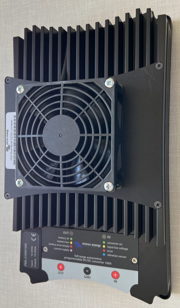
We charge our leisure batteries from solar panels on our roof and/or the engine alternator when we drive. However, this is not so successful when there is little sunlight (e.g. in short winter days or in an overcast tropical rainy season) and we are not driving long distances. We can run the engine without driving, but this can take a while. We would therefore like to charge our leisure batteries more quickly from the engine alternator -whether driving or running the engine static. To do this I installed a Victron Buck Boost DC-DC Converter, you can see more information on this unit at Victron Energy.
The existing system
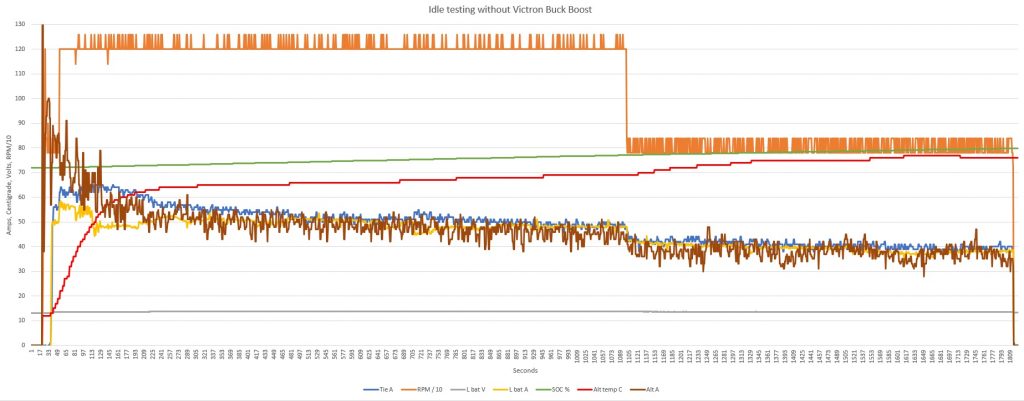
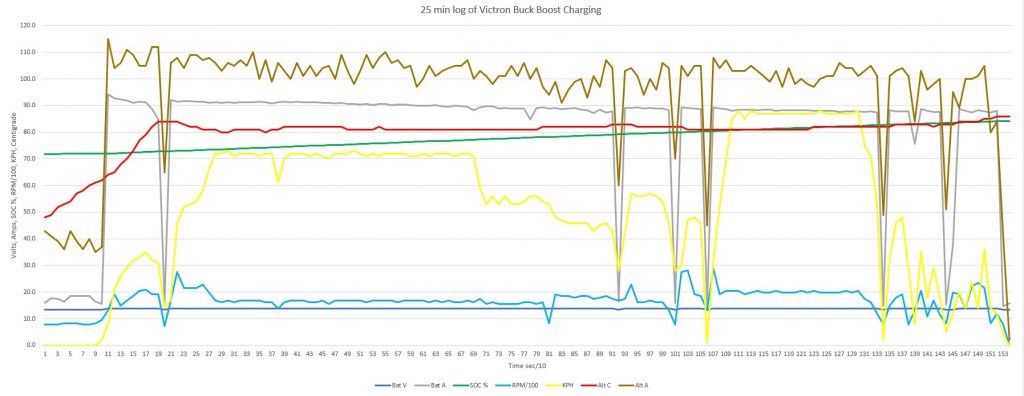
Prior to installing the Victron Buck Boost we would get a maximum charge current of 70 amps when the leisure batteries were at about 55% charge. This current would quickly drop as the batteries were charged, see graph below. The Victron Buck Boost should significantly increase these charge currents, resulting in a faster charge.
We have three Victron 90 Ah Lithium-Ion batteries. Each battery has a recommended charge current of up to 45 amps (maximum 270 amps!). The three batteries are wired in parallel, so a charge current of up to 135 amps is acceptable (810 amps maximum!). Our solar charging maximum output is approximately 30 amps (400 watts of solar panels), so a 100 amps charge from the Victron Buck Boost in addition to the solar is acceptable.
The installation
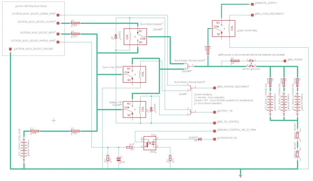
We already have a split charge relay system (Victron Cyrix Li-ion 230 amp) to charge the leisure batteries, with an additional relay which I can connect for winching and jump-starting the starter battery if required. I wanted to maintain this as a back-up should anything happen to the Victron Buck Boost. I have therefore installed a marine change-over switch so I can select the existing system or the new Victron Buck Boost. On the Victron Buck Boost circuit I have also installed a relay to allow winching and jump starting from the leisure batteries.
The Iveco Daily has an ‘alternator in operation’ output from pin 8 of the 20 pin body builder’s connector. This is useful because it goes to 12V when the alternator is actually working ,not just when the ignition is ‘on’. If the engine were to stall or the alternator fail (slipping fan belt etc) the output goes to 0V even with the ignition on. I have used this as means to ensure the Victron Buck Bosst is only switched on when the alternator is in operation.
As you may have seen with some of my other modifications (see here), we have a few Arduino computers on a network around the truck controlling various things. To add to this network I have installed:
(i) a temperature sensor and a current sensor to the alternator that can be monitored with the Arduinos; and
(ii) a control for the Victron Buck Boost from one of the Arduinos;
The Victron Buck Boost does have a ‘Current source’ mode where a voltage between 0V and 2V can control the output current between minimum and maximum. I have therefore made a small circuit that is attached to a Pulse Width Modulated (PWM) output from one Arduino. This circuit uses a smoothing capacitor and voltage divider to provide a 0V to 2V output signal based on the PWM output for controlling the Victron Buck Boost. At present I have not found a need to control the current output with the Arduino, but I have the option in the future should I wish too. In addition, the circuit has an opto-isolator that is controlled by the ‘alternator in operation’ signal. This means the Arduino can control the output of the Victron Buck Boost whenever the alternator is in operation.
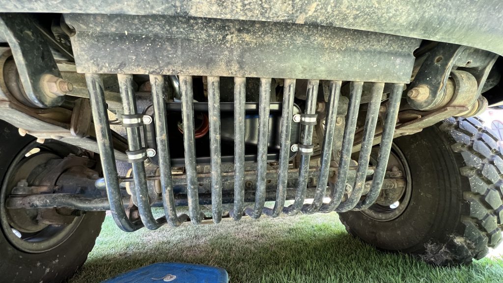
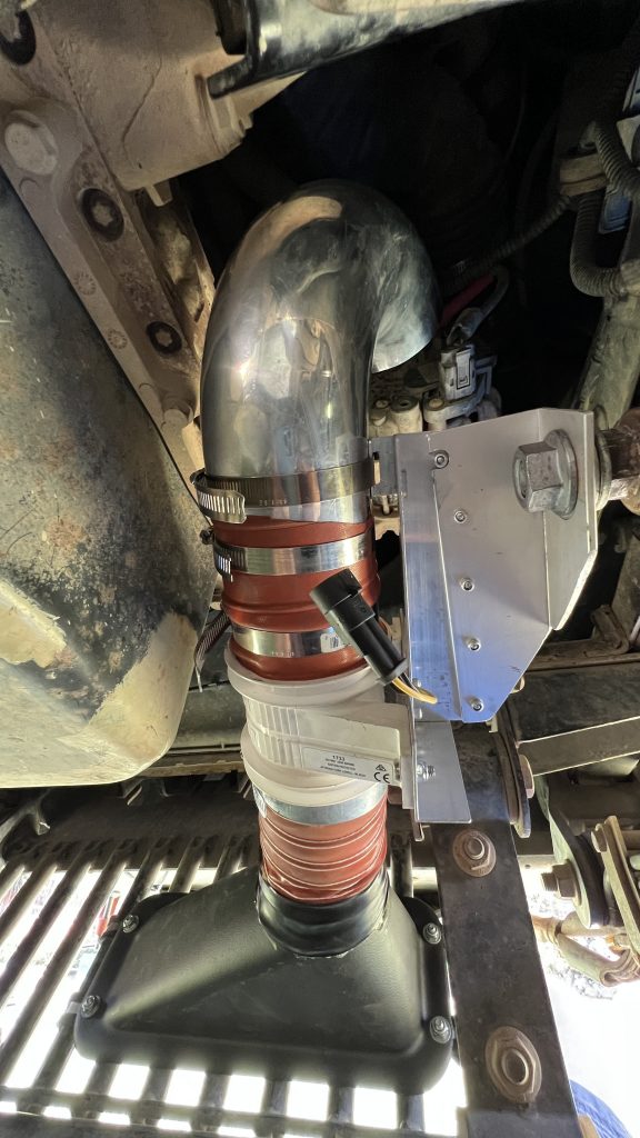
As the alternator will be working hard with the Victron Buck Boost pulling 100 amps from it, I have added additional cooling for the alternator. I have used 3” (76 mm) piping from a ram-air scoop fitted to the radiator guard, through an electric bilge vent fan and routed it to blow onto the rear of the alternator. Alternators suck air in from the rear, over their diode pack and electronics, through the body of the alternator and expel it out at the front. The bilge fan is controlled by another Arduino which turns the fan on when the alternator temperature reaches 80C (maximum alternator temperature allowed is 110C, Bosch/Iveco limit).
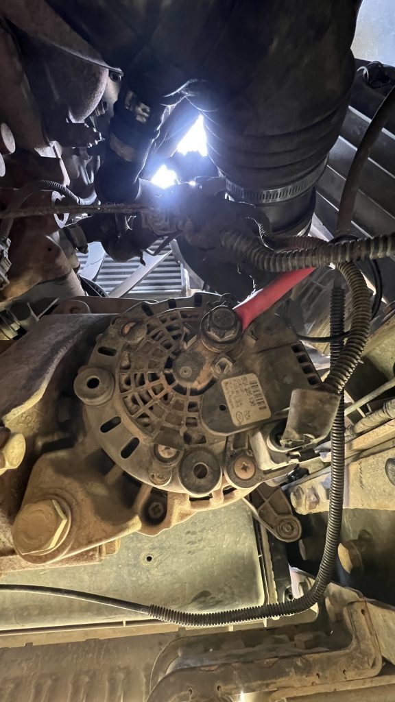
The temperature sensor is attached to the output terminal of the alternator (from my testing, this is the hottest part of the alternator).
During testing, idling at 1200 rpm, if the current was above 80 amps the alternator temperature would increase to over 100C. With the bilge fan, the alternator has not gone above 85C, even when outputting 130 amps! I have the Arduino configured to turn off the Victron Buck Boost if the any of the following criteria are met:
- alternator temperature exceeds 105C.
- alternator current exceeds 130 amps. (The alternator is rated at 140 amps)
- leisure battery voltage exceeds 14.2V and the State of Charge = 100%.
The recommended maximum charge voltage for the lithium batteries is 14.5V however 14.2V is considered better for battery life. I have set the Victron Buck Boost to charge to a maximum voltage of 14.4V so that it produces the maximum charging current for as long as possible (the current flow drops as the battery voltage increases). I have found this gives the fastest charging profile.
The final control the Arduinos have, is to only turn the Victron Buck Boost on when the engine rpm is above 1000 rpm. This gives the alternator a chance to produce the high currents required.
The Victron Buck Boost is also connected to the leisure battery BMS. This can also turn off the Victron Buck Boost if it detects an issue in the leisure batteries that requires charging to stop.
Results
Prior to the Victron Buck Boost installation it would take approximately 4 to 5 hours of driving to recharge the leisure batteries from 50% to 100% (depending on solar output). With the Victron Buck Boost this has been reduced to approximately 1.5 hours!
Note on Victron Alternator Video
Finally… I often get asked about the Victron video on YouTube of the testing of alternators charging lithium batteries. In my opinion this video is VERY misleading and seems to be a marketing tool for their special alternators!
First, vehicles do not have 1:1 ratio pulleys between the crank shaft and alternator. They are normally between about 2.5 or 3 to 1. Look at your engine and see how small your alternator pulley is compared to the crankshaft pulley. With an engine idling at 800 rpm, the alternator is already doing between 2,000 and 2,400 rpm which Victron admit is fine.
Secondly, your lithium batteries are unlikely to be directly connected to the alternator with a short wire. They will probably have several metres of wire from the alternator to the batteries. This cable length acts as a current limiting resistor. While there is a high voltage difference between the alternator and battery, there will be a large current flow = a large voltage drop = reduction of current flow (V= I x R, Ohm’s law).
You may be interested in our lithium battery upgrade <click here> and our page on whether it’s worth carrying a generator <click here>.