
We have several Arduino computers around the truck doing various tasks. In response to our social media posts, we are often asked what we use them for and how we did it. So far we have only shared information on the following Arduino based projects (click on the link below to go to its page):
We have been reluctant to share more information because we don’t want to be inundated with emails requesting support for projects copying our systems. I am not a software engineer and this has just been a hobby for me during the evenings. The systems are constantly evolving and there are some software bugs. A professional software engineer would certainly laugh at the way the code is written, but it has worked so far for us. And my programming knowledge is getting better all the time! Some technical code has been obtained from the internet and Arduino books available on Kindle. Resources I have found useful are:
- https://forum.arduino.cc/
- A great deal of programming information is available here
- www.GitHub.com
- Lots of useful libraries for Arduino coding
- www.Victronenergy.com/live/open_source:start
- Example programs showing how to interface to Victron products
- https://copperhilltech.com/
- Excellent books, hardware and free software for interfacing Arduinos using CAN
- Prototyping with Arduino – available on Kindle
- SAE J1939 ECU Programming & Vehicle Bus Simulation with the Arduino – available on Kindle
- – downloadable from their website, versions for the Uno and Mega and another for the Due.
- https://4dsystems.com.au/
- This is the display system we use, great interface for programming the display, loads of documentation and good support.
- www.Google.co.uk
- There are so many people using Arduinos for various projects a quick google can normally find a solution to a problem you are having.
So on the understanding that:
– this is strictly for general information only, and
– it is NOT guaranteed to work, and
– you use it at your own risk (and all the other warnings/provisos you can think of)
this is how our systems do their thing….
Programming
I’m not going into the full details of how I program the Arduino computers, it’s quite straightforward and there are plenty of examples on-line. I use the Arduino IDE which is available as a free download from here: https://www.arduino.cc/en/main/software
For the 4D Display 7” touch screen I use their IDE which is also available as a free download from here: https://4dsystems.com.au/workshop4
For editing some of the libraries we also used Microsoft Visual Studio.
System Overview
In Cuthbert we have 6 networked Arduino computers doing different jobs. They all communicate with one another using the ARD1939 – SAE J1939 Protocol Stack for Arduino downloaded from the Copperhill Technology website. I will refer to this as the Controller Area Network (CAN) from here on.
- AFAM Arduino – Due
- It has replaced the original Iveco ‘AFAM’ computer and controls the vehicle’s differential locks (centre, rear and front) and power take-offs (if fitted).
- Display Arduino – Mega
- This Arduino is on the dashboard and is used to interface the other Arduinos to the 4D Display 7” touch screen.
- Fuse Box Arduino – Due
- As the name would imply, it is in the fuse box.
- It captures the following information and shares it on the CAN:
- Victron BMV battery monitor serial data.PWM solar charger output current.
- Fresh water level.
- Grey water level.
- Smoke/LPG/Carbon Monoxide detection (work in progress).
- Battery Box Arduino – Due
- Guess where this is!
- It captures the following information and shares it on the CAN:
- Victron MPPT solar charger serial data.
- Current on the cable between the starter battery and leisure batteries which I will refer to as ‘Tie Current’.
- Current on the ‘shore power’ cable.
- Current output from the inverter.
- Water flow rate into the fresh water holding tank.
- Water flow rate out of the fresh water holding tank.
- Controls the water filling using a solenoid valve in the water filling pipe.
- Controls a back-up relay for connecting the starter and leisure batteries.
- Can isolate all charging of the leisure batteries.
- Monitor Arduino – Due
- This is a small hand portable device with colour LCD display.
- It displays:
- Water use data.
- Battery monitor data.
- MPPT solar charger data.
- PWM solar charger data.
- Tie Current.
- System time.
- GPS data.
- GSM Arduino – Mega
- It does the following:
- Allows communication with Cuthbert by text messaging.
- Provides position reports by text.
- Provides GPS data to other Arduinos.
- Provides a clock for other Arduinos.
- Interfaces to the engine ECU and can:
- Shut the engine down.
- Engage a vehicle speed limiter of 30 kph.
- Tell the ECU to detect when the vehicle has stopped and automatically shut down the engine.
- It does the following:
Controller Area Network (CAN)
All the Arduinos communicate on a Controller Area Network (CAN). I chose CAN as it has many advantages over the Serial port communications available on the Arduinos. CAN is used throughout the automotive industry as it is fast, reliable and easy to wire, all properties that made it ideal for this application. I will not go into the finer details of CAN here, there is a lot of information about it on-line.
I have used three tyres of hardware for the CAN interface on our Arduinos:
- For the Arduino Mega I have used NiRen MCP2515 CAN modules. They are extremely cheap, about £1.50 each and work quite well.
- For the Arduino Due, I have used Copperhill Technology “Dual CAN Bus Interface for Arduino Due With Extended Power Range” interfaces. They allow the Due to be connected to two separate CAN networks and include a power supply so the Due can be powered by the vehicles 12V supply.
- For my latest Arduino Due interfacing I am now just using a voltage level shifter and MCP2551 high speed CAN transceiver chip.
For the CAN software I have used the Copperhill Technology ARD1939 – SAE J1939 Protocol Stack for Arduino. This software is free to download and use from their website. There are two versions of this software:
- The first version is for Arduinos that are using a MCP2515 CAN module. The MCP2515 chip on the module handles all the data processing to communicate with the CAN.
- The second version is only for the Due. The Due has a CAN port within its processor and this version of software allows the Due to do all the functions of the MCP2515 chip. This means that all that is required between the Due and the CAN is a high-speed CAN transceiver chip, greatly simplifying the interface.
The Copperhill Technology ARD1939 – SAE J1939 Protocol Stack for the Arduino is a ‘full implementation’ of the ARD1939 – SAE J1939 standard and was chosen so our Arduino CAN network is compatible with the Iveco CAN. In the future, the two CANs can be connected. This will allow engine and vehicle data to be shared with the Arduinos.
The Mega has limited computing power and memory compared to the Due, but the Mega operates at 5V which is easier to interface with many modules than the Due at 3.3V. However, I am planning to swap out the Megas for Dues to make use of the extra computing power and simpler CAN interface electronics.
Because of the Megas limited memory, the ARD1939 – SAE J1939 Protocol Stack message length needs to be limited from the standard 1785 bytes. For our network, I have limited the message length to just 75 bytes. Once all the Megas have been replaced with Dues, this limitation can be removed and the full 1785 Byte length could be used. However, at present all the CAN messages are 8 bytes or less and so do not require the use of the transport protocol and so the 75 byte limitation is of no consequence.
The ARD1939 – SAE J1939 Protocol Stack allows for the full functionality of the standard, there are a lot of variables to set and the table below shows the configuration and the current messages that I send of the CAN:
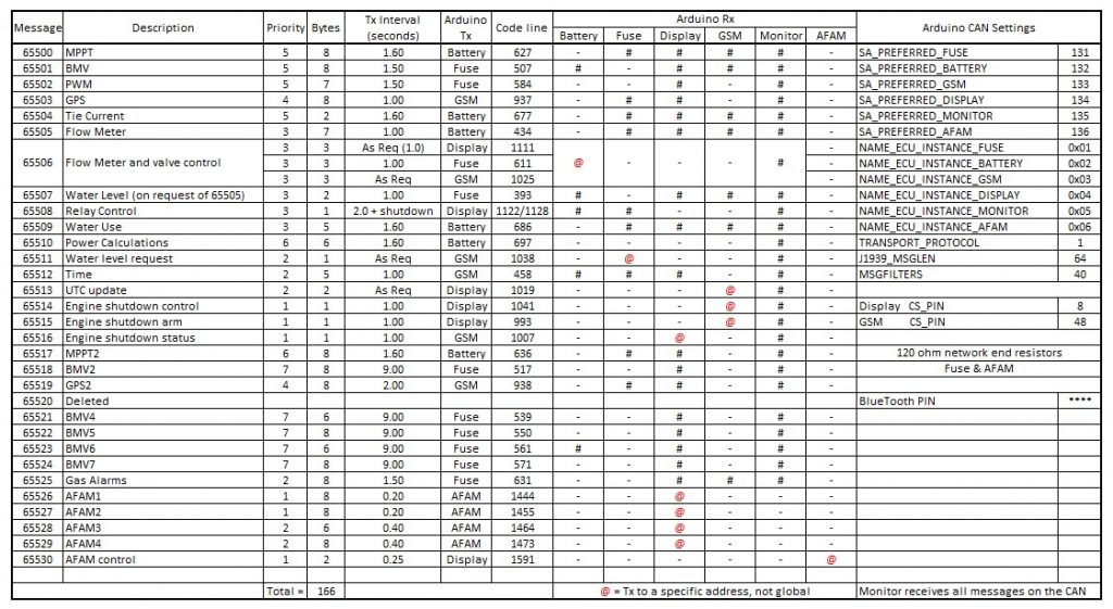
The address are variable so that there are no conflicts between different nodes on the CAN. The preferred address and ECU instance (name for the node) that I have set for the Arduinos are all listed in the table above. The preferred address range (SA_PREFERRED, ADDRESSRANGEBOTTOM, ADDRESSRANGETOP), message length (J1939_MSGLEN), preferred address (SA_PREFERRED) and ECU instance (NAME_ECU_INSTANCE) are all set within the ARD1939.h file.
So that my CAN is compatible with the Iveco CAN, I have chosen to run the network at the J1939 CAN standard baud rate of 250k BPS, this setting is made in the can.cpp file.
That is all the generic information on our Arduinos. For more detailed information on each of the Arduinos follow the links below:
Battery box Arduino (will be posted soon…)
GSM Arduino (will be posted soon…)
Display Arduino (will be posted soon…)
Rear Display Arduino (will be posted soon…)