
Sadly after several days of operation my power supply has stopped producing 48V. It appears IC2 has stopped driving the gate of Q4, gate voltage 0V. I will need to investigate this further to find the reason why. Unfortunately, it could be a while until I can get replacement components as we travel. Once I have solved the issue I will post it up here.
In my Starlink-user history I have modified both the round and the rectangular dish to run on DC. My Starlink DC Power Supply POE Injector should make modifying the rectangular dish easier. These modifications can save power, as an inverter is no longer need whilst off-grid. Although inverters are efficient (typically 96%) they do consume power to operate. A typical inverter can use 10W or more to power itself, then there is the additional 1.5W in efficiency losses. This means the average 35W power required by Starlink, increases to about 46W from the battery with an inverter – that’s an overall increase of around 31% in power consumption! You can read more about my DC conversions to the round dish power supply and rectangular dish router here.
In designing and building my own DC power supply, my design considerations were:
- fit inside the rectangular dish router (for a much cleaner modification with no wires between various power supplies and circuit boards);
- good circuit protection for the transient voltages that can be encountered in a vehicle;
- Input voltage range for 12 V vehicle electrical systems;
- 48V output current of 2 A (required for the rectangular dish);
- 12V output current of 1.25 A (required for the rectangular dish router);
- 48V and 12V output over voltage protection;
- easily interfaceable remote power control to turn the power supply on/off;
- include an on-board POE injector so Starlink can be used without the supplied router;
- low voltage input capability (to maintain full functionality during an engine start, or on a long cable if there is significant voltage drop) and;
- Current sensor interface so an Arduino or other small computer can monitor power consumption.
Circuit Description
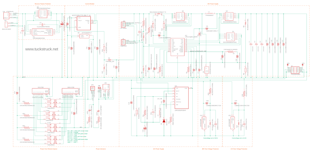
The full size circuit diagram image can be downloaded from my Dropbox here.
Reverse Polarity Protection
The first stage of the power supply design is reverse polarity protection. If you were to accidently try and jump-start the vehicle with the jump-leads connected the wrong way around, you could damage the power supply. This is a normal consideration for automotive electronics. A simple solution would be to use a diode to block any reverse current. However, diodes are not very efficient and the whole point of this project is to make a more power-efficient power supply. Luckily, Texas Instruments make the LM74610 to create a ‘perfect diode’ using a FET just for this type of application. The LM74610 ‘Zero IQ Reverse Polarity Protection Smart Diode Controller’ controls a FET on the input stage and ‘turns off’ the power if reverse current is detected.
Voltage Spike Protection
Often in vehicle systems there are voltage spike protection components to restrict the maximum voltage spike allowed into the system. The AEC-Q100 ‘qualified for automotive applications’ LM5121 power supply that I have used in the design can handle input voltages up to 65V, so does not need additional protection in 12V (or 24V) vehicle applications. The 12V power supply is protected by the 48V supply as it is powered from the 48V power supply.
Over Voltage Protection
The 48V and 12V power supplies have over voltage protection circuits that will shut down the supply if an excessive output voltage is detected. Shut down thresholds are approximately 59.5V for the 48V supply and 13.9V for the 12V supply.
Power Supply Design
Both the 48V and 12V power supplies were designed using the Texas Instruments ‘WEBENCH® POWER DESIGNER’, see: here
48 V Supply
A LM5121-Q1 ‘Wide Input Synchronous Boost Controller with Disconnection Switch Control’ is the basis of the 48V power supply. It boosts the input voltage to the required 48 V.
My design criteria were:
- Iout 3.5 A Maximum Output Current
- VinMax 18 V Maximum input voltage
- VinMin 10 V Minimum input voltage
- Vout 48 V Output Voltage
- Ta 30 C Ambient temperature
The power supply chip has a feature to turn itself off if the supply voltage drops below a certain level. This can be useful in battery applications where you do not want to overly discharge the battery. However, I have deliberately set this to a cut off voltage of 7.2V because I do not want the power supply to shut down when starting the vehicle or if using a long power cable (with significant voltage drop). Therefore, you will need to monitor your battery’s charge level to ensure it does not become damaged from over discharging. If you have a lithium battery, your battery management system should turn off the load before the battery is overly discharged.
12 V Supply
A LMR16020 ‘SIMPLE SWITCHER® Step-Down Converter’ is used to produce the 12 V required for the router’s circuitry from the 48V output. Using the 48V output ensures a stable 12V supply even with a low input voltage below 12V. This means in a vehicle, the supply voltage can drop below 12V during an engine start and not affect the 12V supply. I have set the output voltage to 13V, as that is the measured output voltage of the Starlink power supply.
My design criteria were:
- Iout 1.5 Maximum Output Current
- VinMax 49.0 Maximum input voltage
- VinMin 47.0 Minimum input voltage
- Vout 13.0 Output Voltage
- Ta 30.0 Ambient temperature
POE Injector
The POE Injector section is a copy of the one I designed to plug onto the Starlink power supply, see here.
Current Monitor
There is a ACS712 current monitor in the circuit so that the current draw of the Starlink can be monitored. The output of the ACS712 is capped to 3.3V limits for interfacing to the analogue input of Arduinos or other small computers.
JP1 – 12V On/Off
The JP1 link on the PCB can be used for turning off the 12V supply when using the power supply as a POE injector and the 12V supply is not needed.
JP2 – LED on/off
To turn off the LEDs remove the link form JP2.
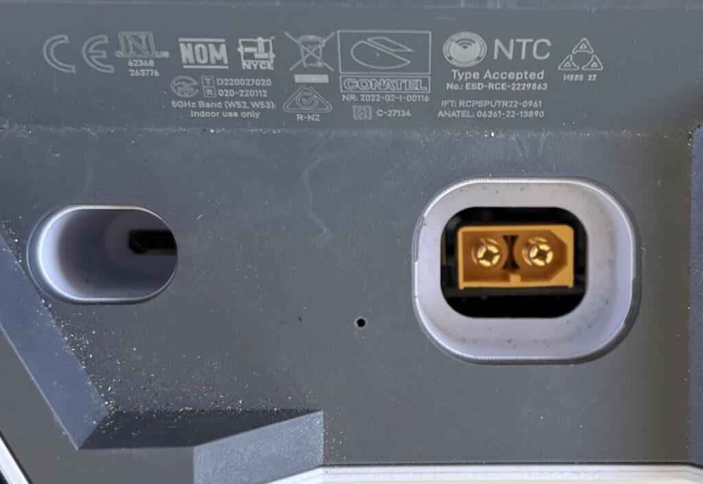
J1 – 12 V Input Socket
To connect the supply voltage there are a few options:
- J1A location is designed for an XT60PW-M socket;
- J1B location is designed for a screw terminal; or
- wires could be soldered directly to the PCB using the holes for J1A or J1B.
J2 Interface
The J2 connector is used for remote control/monitoring. The pins are wired as follows:
- Pin 1 – Shut down the power supply by applying 3.3V to 5V (can be driven directly from an Arduino port).
- Pin 2 – Ground
- Pin 3 – Shut down by connecting this pin to ground (can be driven directly by an Arduino port).
- Pin 4 – Analogue output from ACS712 current sensor
J3 – 12 V Outlet Socket
The 12V output can be taken from:
- J3A location is designed for a screw terminal;
- J3B location is designed for an XT60PW-F socket; or
- wires could be soldered directly to the PCB using the holes for J3A or J3B.
Note: if you are installing the power supply into the router the XT60PW-F socket or screw terminals will touches the WiFi PCB, it would be better to use a low profile screw terminal on not install a socket or screw terminal in this location.
J4 – Power Supply Output Connector
J4 is positioned to connect into the Starlink router PCB. The pin allocations are:
- Pin 1 = solder pad 1 – used for LED on original power supply.
- Pin 2 = solder pad 2 – used for LED on original power supply.
- Pin 3 = 12 V DC supply.
- Pin 4 = Negative.
- Pin 5 = Negative.
- Pin 6 = 48 V DC supply.
- Pin 7 = Ground.
- Pin 8 = 48 V DC supply.
Fusing
With the power supply being used to power the rectangular dish and Starlink router, you should protect the power supply with a 10 A fuse for 12 V systems.
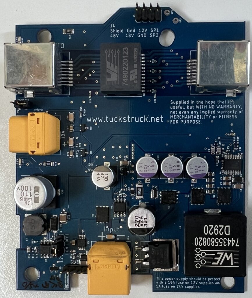
Prototype PCB Specification
The prototype was built on a 1.6 mm thick FR-4 TG130 PCB with 2oz copper layers and HASL (Hot Air Solder Level) solder pads. I chose 2 oz to ensure high power operation and the thicker copper also helps with chip cooling.
Availability
As we are travelling full time it is impractical for me to start to manufacture these units. However, I am providing all the information you need to make one yourself or have someone else make one for you. I am not going to charge for any of the information. I am not a professional electronics engineer and this is therefore a ‘use at your own risk’ option.
The PCB can be ordered from Seeed Studio here or if you want to order the PCB from another supplier I have uploaded the Gerber files to my Dropbox here.
If you want to use a stencil to assist with applying solder paste, these are the settings I used on Seeedstudio for this PCB:
- PCB Dimensions – 10.0cm * 15.0cm Frameless – eff.8*13
- Sides – Top
- Stencil quantity – 1
- Fiducial Mark – No fiducial
- Thickness – 0.12 mm
- Polishing Technique – Polished
The Zipped Gerber file required for the stencil is the same as the one used for the PCB.
Here is the Bill Of Materials (BOM) where the components can be ordered click here.
This is on the Digikey Mexico website but they can supply from Digikey in other countries too (the Mexico website actually ships from the US).
The customer reference in the BOM ties up with the circuit diagram and PCB for the component. This should be printed on the packet when you receive it to make construction easier.
Circuit Modifications
If you do not require reverse polarity protection you can delete: IC1, Q1 and C2 but will need to solder a shorting link across the gap left by Q1.
If you do not need LED1 (48 V on) you can also delete R17.
If you do not need LED2 (12 V on) you can also delete R18.
The PCB has been designed to take an XT-60PW-M plug for the supply input at J1A instead of a screw terminal (J1B) if required. Digikey do not stock the XT-60PW-M, I purchased them from RS Components: here
The PCB has been designed to take an XT-60PW-F socket for the 12V output at J3A instead of a screw terminal (J3B) if required. Digikey do not stock the XT-60PW-F, I purchased them from RS Components: here
If you need mating XT-60 plugs and sockets here are the links I used to buy them:
Male Plug: here
Female Socket: here
If you are not going to plug it into the Starlink WiFi, you can delete J4.
If you are going to plug it into the Starlink WiFi and do not require the POE, you can delete the following components: C22, C23, R13 to R16, T1, ‘Router’ and ‘Dish + POE’ RJ45 sockets.
Note: I have designed the PCB to fit inside the Router with all the components installed. The POE Injector on the power supply will not use any power while the power supply is plugged into the WiFi board within the router, so there are no power savings to be gained by deleting any of these components.
I have not ‘designed’ or tested this circuit design for use other than on 12V for a rectangular dish with snow melt off. The following could be tried but I cannot be sure it would work! It should handle snow melt on the rectangular dish. The components have input voltage tolerances that are compatible with 24V vehicles. On 24V the supply would use half the current and so a 5A fuse would be more appropriate. The output power of the supply could possibly supply up to 3.5A and so it may be capable of supply enough power for a round dish but would get very hot! The round dish would require a larger fuse, 15A on 12V, 7.5A on 24V. The output voltage could be adjusted to 56V by changing the value of R8 to 46KΩ (the 12V power supply circuit should handle this higher voltage ok).
Assembly
WARNING: 48V DC is a dangerous voltage and the power supply can store energy for a long time after it has been disconnected from the power. Do not attempt to use this power supply/POE injector if you are not sure about what you are doing.
The PCB is a little complicated, and some of the components are very small: 1 mm x 0.5 mm. It could be manually soldered, or a hot air rework station could be used. However, I used the frying pan reflow method as I did for the POE injector project. I used a stencil to help apply solder paste to the PCB (also available from Seeed Studio – see link above). The solder paste I used was ‘solder paste no clean 63SN/37PB’ see here.
After applying the solder paste to the top of the PCB, I positioned all the surface mount components on the board, starting with the smallest.
The two LEDs need to be installed the correct way around, Anode to + and Cathode to -. The top of the LED has a small stripe on the Cathode – end, see data sheet, that should be positioned next to the dot on the PCB. LED data sheet here.
The pulse transformer T1 should be installed with the round dot on top of the case aligned with the dot on the PCB.
The large capacitors should be aligned with the printed shape on the PCB.
The diodes have a stripe on the Cathode end, which should be aligned with the dot on the PCB.
The dot on top of IC1 and IC2 should be orientated with the white dash on the PCB.
The dot on U1, Q1, Q2, Q3 and Q4 should orientate with the white dot on the PCB.
With all surface mount components fitted to the top surface of the PCB, I heated the PCB in a frying pan (a small piece of aluminium foil under the PCB to protect the frying pan). I managed (more or less) to replicate the heat profile recommended by the solder paste manufacturer by adjusting the heat while monitoring the temperature using an IR temperature sensor – it wasn’t perfect temperature management, but worked. The temperature profile is on a card included with the solder paste or can be seen in the data sheet here.
Once the solder had melted and flowed, I removed the PCB from the frying pan and left it to cool. Finally, I manually soldered the remaining components – the through-hole components – onto the PCB.
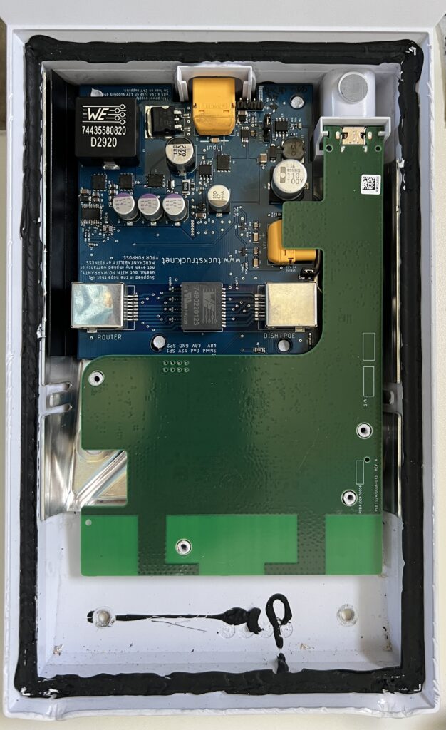
Use
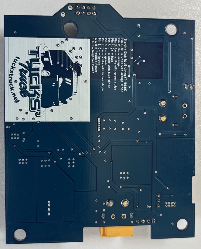
This power supply can be fitted inside the rectangular dish router in place of the mains power supply. It can also be used ‘stand-alone’ as a POE injector by plugging the dish into the RJ45 socket labelled ‘Dish + POE’ and plugging a router into the router RJ45 socket. The Dish cable should be wired to T-568B colour code (this is standard for the round dish). This T-568B colour code is printed on the back of the PCB for your convenience. If you are using it as a ‘stand-alone’ POE injector, you can use the 12V power supply output to power a 12V router or switch. I have designed the 12 V power supply to supply up to 1.5A; do not exceed this value.
Cooling
It is best to mount the power supply so that air can circulate around the PCB and heat can dissipate. If you are using it stand-alone in a high-power mode (e.g. with snow melt on) then consider adding additional cooling.
Testing
I have only used this power supply with my rectangular dish on a 12V vehicle supply without the snow melt being turned on. In theory it should be capable of running snow melt on the rectangular dish.
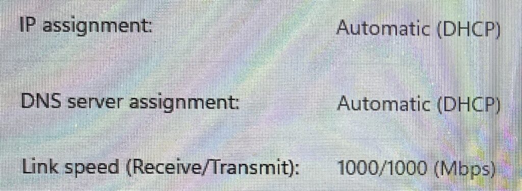
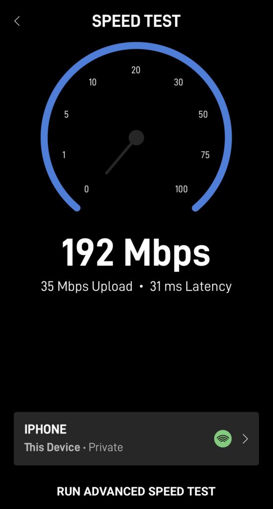
In POE mode it negotiates a 1000/1000 (Mps) ethernet connection.
I also achieved resonable data speeds from the Starlink through the POE to my laptop.
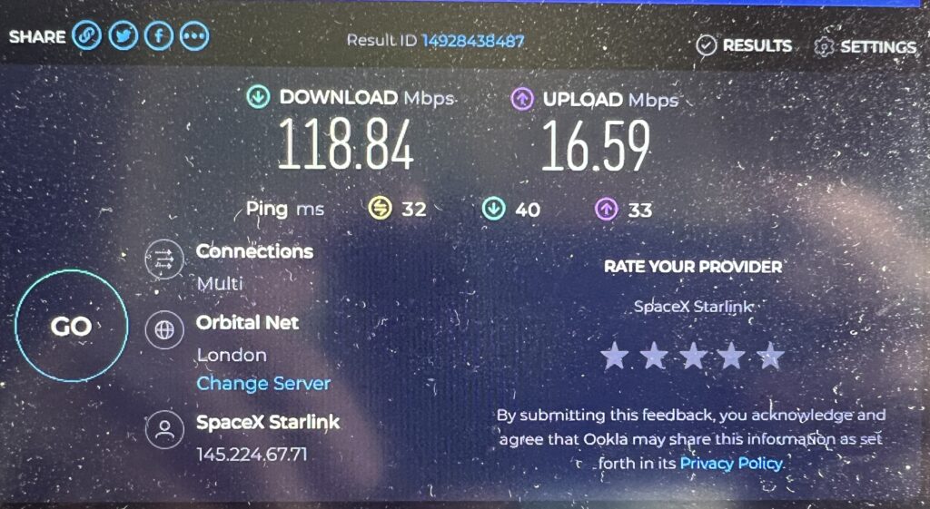
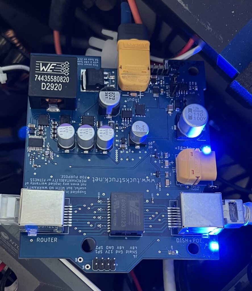
Installed in the router.
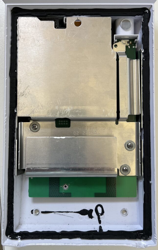
With the power supply fitted in to the router, I got acceptable speeds.
If you sign up for Starlink with our referral code (click here), we will each receive one month of free service 30 days after activation. For more information on how it works, check out Starlink support topics here.